GE JP201CBSS Use and Care Manual - Page 11
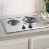
Typical installation location., This counter unit must be installed, with the control knobs toward
 |
UPC - 084691798118
View all GE JP201CBSS manuals
Add to My Manuals
Save this manual to your list of manuals |
Page 11 highlights
Safety Instructions Operating Instructions Care and Cleaning Installation Instructions Troubleshooting Tips Consumer Support Typical installation location. (if installing the cooktop over a GSM2100 dishwasher, go to the next page) Read these instructions completely and carefully. Dimensions and Clearances ge.com A: 21 1⁄2″ B: 16 5⁄8″ C: 19 15⁄16″ D: 15 15⁄16″ E: 16 1⁄8″ 13″ Max. 30″ Min. F: 20 1⁄8″ G: 10 1⁄16″ H: 3″ J: 2″ Min. K: 2 3⁄4″ Min. A B H D C J 13⁄4″ Min. clearance to side wall F G E 13⁄4″ Min. clearance to side wall K Unit and cutout dimensions This counter unit must be installed with the control knobs toward the front edge or the side. Counter space must be provided for installation of the counter unit. When choosing a location, consider the following: I The cooktop should be easy to reach and lighted with natural light during the day. I To eliminate the risk of burns or fire by reaching over heated surface units, cabinet storage space located above the surface units should be avoided. If cabinet storage space is to be provided, the risk can be reduced by installing a range hood that projects horizontally a minimum of 5″ beyond the bottom of the cabinets. Cabinets installed above the counter unit may be no deeper than 13″ and must be at least 30″ above the cooktop. I To insure accuracy, it is best to make a template when cutting the opening in the counter. See the following illustration and chart for all necessary dimensions. The following minimum clearances must be maintained: I 23⁄4″ minimum clearance between the front edge of the counter unit and the front edge of the counter. I 30 ″ minimum vertical clearance from the cooktop to the nearest overhead surface. I 15 ″ minimum vertical clearance to adjacent cabinets. I 11⁄2″ minimum vertical clearance between the bottom of the cooktop and any combustible material, i.e. shelving. 11


