GE JP3036SLSS Installation Instructions
GE JP3036SLSS Manual
 |
View all GE JP3036SLSS manuals
Add to My Manuals
Save this manual to your list of manuals |
GE JP3036SLSS manual content summary:
- GE JP3036SLSS | Installation Instructions - Page 1
Installation 30 and 36" Instructions Electric Cooktop - Radiant Excludes Down-Draft Models If you have questions, call GE Appliances at 800.GE.CARES (800.432.2737) or visit our website at: GEAppliances.com. BEFORE YOU BEGIN Read these instructions carefully and completely. • IMPORTANT - Save these - GE JP3036SLSS | Installation Instructions - Page 2
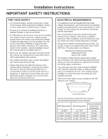
Instructions IMPORTANT SAFETY INSTRUCTIONS FOR YOUR SAFETY • For Personal Safety, remove house fuse or open circuit breaker before beginning installation. Failure to do so could result in serious injury or death. • Be sure your cooktop is installed properly by a qualified installer or service - GE JP3036SLSS | Installation Instructions - Page 3
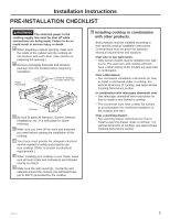
Manual, Installations, etc. in a safe place for future reference. D Make sure you have all the tools and materials you need before starting the installation of the cooktop. E Your home must provide the adequate electrical service See microwave installation instructions for how to install a microwave - GE JP3036SLSS | Installation Instructions - Page 4
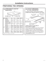
Installation Instructions PREPARING THE OPENING 1 APPROXIMATE COOKTOP DIMENSIONS X Y Cooktop Z 30" models: 19 1/4" 36" models: 18 7/8" 30" (black) or JXTR32W (white) to reduce the cutout opening for installation of this cooktop. This kit may be ordered from your dealer or directly from - GE JP3036SLSS | Installation Instructions - Page 5
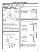
30 gage (0.0125") thick. A ventilation hood may be installed above the cooktop. See the ventilation hood installation instructions for the appropriate dimensions and clearances. 4 Make sure the Also, an access panel is required for the junction box, hold-down brackets, and service. 31-11072-1 5 - GE JP3036SLSS | Installation Instructions - Page 6
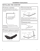
Installation Instructions INSTALLING THE COOKTOP 1 VERTICAL CLEARANCE Install an approved junction box where it junction box must be located where it will allow considerable slack in the conduit for serviceability. 2 PROTECT SURFACE OF COOKTOP Place a towel or tablecloth onto the countertop. Lay - GE JP3036SLSS | Installation Instructions - Page 7
kit WB01X24570 with wing nuts and brackets by calling 800.GE.CARES. See diagram for instructions. Open the cabinet door. Install the second screw through the bracket and tighten. Then tighten the first screw. Install thumbscrew until it touches the bottom of the countertop. 6 ELECTRICAL - GE JP3036SLSS | Installation Instructions - Page 8
Installation Instructions INSTALLATION-ELECTRICAL CONNECTIONS GROUNDING INSTRUCTIONS: The ground wire in the the cooktop surface. B Turn on the power to the cooktop (refer to your Owner's Manual). Verify that all surface burners operate properly. C Check that the circuit breaker is not tripped - GE JP3036SLSS | Installation Instructions - Page 9
Radiante Excluye los Modelos de Flujo Descendente Ante cualquier duda, llame a GE Appliances al 800.GE.CARES (800.432.2737) o visite nuestro sitio Web en: nivelar Broca perforadora de 1/8" y taladro eléctrico o manual PARTES INCLUIDAS Gafas de seguridad 4 Tornillos (WB01X1137) Cinta - GE JP3036SLSS | Installation Instructions - Page 10
Instrucciones de instalación INSTRUCCIONES DE SEGURIDAD IMPORTANTES PARA SU SEGURIDAD • Para su seguridad personal, retire los fusibles de su hogar o bien desconecte el cortacircuitos antes de comenzar con la instalación. El no hacerlo puede resultar en lesiones serias o incluso la muerte. • Asegú - GE JP3036SLSS | Installation Instructions - Page 11
ON Estufa C Asegúrese de colocar todo el material impreso, Manual de propietario, Instalaciones, etc., en un lugar seguro para referencia correcto de su estufa. (Consulte la sección de requisitos eléctricos). F Cuando instale la estufa en su hogar, asegúrese de cumplir todos los códigos y reglas - GE JP3036SLSS | Installation Instructions - Page 12
(blanco) para reducir el recorte de la abertura para la instalación de esta superficie de cocción. Este kit puede ser ordenado a su vendedor minorista o directamente a GE Appliances en www.geappliances.com. 4 31-11072-1 - GE JP3036SLSS | Installation Instructions - Page 13
Instrucciones de instalación PREPARACIÓN DE LA ABERTURA (Cont) 3 DESPEJES MÍNIMOS HASTA LAS PAREDES Y GABINETES ADYACENTES Profundidad máxima de 13" de gabinetes elevados desprotegidos Despeje mínimo de 30" desde la mesada hasta una superficie elevada desprotegida Mínimo de 30" para una - GE JP3036SLSS | Installation Instructions - Page 14
cinta de espuma alrededor del borde externo del vidrio. No superponga la cinta de espuma. Parte inferior de la estufa Cinta de espuma 16" Mín. Instale la caja de conexiones de modo que pueda alcanzarse a través del frente del gabinete. IMPORTANTE: La caja de conexiones debe localizarse en donde el - GE JP3036SLSS | Installation Instructions - Page 15
: Usted puede ordenar un kit de instalación alternativa WB01X24570 con tuercas mariposa y soportes llamando al 800.GE.CARES. Para acceder a instrucciones, consulte el diagrama. Abra la puerta del gabinete. Instale el segundo tornillo a través del soporte y ajuste. Luego ajuste el primer tornillo - GE JP3036SLSS | Installation Instructions - Page 16
todos los objetos que se encuentren sobre la superficie de la estufa. A Encienda la toma de corriente de la estufa (consulte su Manual del propietario). Verifique que todas las hornillas de la superficie funcionen correctamente. A Verifique que el cortacircuitos no esté desactivado o que se haya
-
 1
1 -
 2
2 -
 3
3 -
 4
4 -
 5
5 -
 6
6 -
 7
7 -
8
-
9
-
10
-
11
-
12
-
13
-
14
-
15
-
16
 |
 |

Installation
Instructions
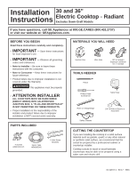
BEFORE YOU BEGIN
Read these instructions carefully and completely.
•
IMPORTANT
—
Save these instructions
for local inspector’s use.
•
IMPORTANT
—
Observe all governing
codes and ordinances.
•
Note to Installer –
Be sure to leave these
instructions with the consumer.
•
Note to Consumer –
Keep these instructions for
future reference.
•
Product failure due to improper installation is not
covered under the Warranty.
•
WARNING
This appliance must be properly
grounded.
•
ATTENTION INSTALLER
ALL COOKTOPS MUST BE HARD WIRED
(DIRECT WIRED) INTO AN APPROVED
JUNCTION BOX. A “PLUG AND RECEPTACLE”
IS NOT PERMITTED ON THESE PRODUCTS.
•
Proper installation is the responsibility of the
installer and product failure due to improper
installation is NOT covered under warranty.
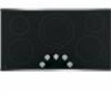
30 and 36”
Electric Cooktop - Radiant
Excludes Down-Draft Models
MATERIALS YOU WILL NEED
TOOLS NEEDED
CUTTING THE COUNTERTOP
If you are installing the cooktop in a solid surface
material such as granite, quartz or any other natural
or synthetic solid surface, we recommend that the
cutout be prepared by a professional cabinet or
countertop installer.
Cooktop cutouts in wood or wood-laminate
countertops may be able to be prepared using a
saber saw and electric drill.
PARTS INCLUDED
If you have questions, call GE Appliances at 800.GE.CARES (800.432.2737)
or visit our website at: GEAppliances.com.
31-11072-1
04-17
GEA
Wire Nuts
Junction Box
Saber Saw
Pencil
Safety Glasses
1/8” Drill Bit & Electric or
Hand Drill
Ruler or Straightedge
Phillips Head
Screwdriver
2 Hold Down
Brackets
4 Screws
(WB01X1137)
Foam Tape
WB06K5042
90º or Straight
Squeeze Connector
for 1” Conduit