GE NX-591E-GSM Instruction Manual - Page 9
Wiring - specifications
 |
UPC - 782136718904
View all GE NX-591E-GSM manuals
Add to My Manuals
Save this manual to your list of manuals |
Page 9 highlights
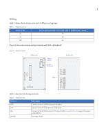
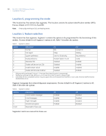
5 Wiring Table 1 shows the maximum wire run for different wire gauges. Table 1. Maximum wire run Length in feet 10 50 100 Wire gauge (connected to NX control panel or NX320E power supply) 20 18 16 Figure 3 shows the module wiring terminals and LEDs on the board Figure 3. Wiring terminals Board front J2 Tamper J1 switch DATA COM Wiring POS terminals TAM LEDs Board back DS1 DS3 DS4 DS5 DS6 XMIT POOR FAIR GOOD BEST SVC SVC2 RXD TXD Table 2 describes the wiring terminals. Table 2. Wiring terminals Terminal DATA COM POS TAMPER Description Connect to the KP DATA terminal of the panel. Connect to the KP COM terminal of the panel. Connect to the KP POS terminal of the panel. Refer to Specifications on page 24 for power consumption. Normally closed.
-
 1
1 -
2
-
3
-
 4
4 -
 5
5 -
 6
6 -
 7
7 -
 8
8 -
 9
9 -
 10
10 -
 11
11 -
 12
12 -
 13
13 -
 14
14 -
15
-
16
-
17
-
18
-
19
-
20
-
21
-
22
-
23
-
24
-
25
-
26
-
27
-
28
-
29
-
30
-
31
-
32
 |
 |
