Genie ChainLift 800 Owner's Manual - Page 10
Rail Assembly for CHAIN DRIVE OPENER, Rail Assembly for BELT DRIVE OPENER
 |
View all Genie ChainLift 800 manuals
Add to My Manuals
Save this manual to your list of manuals |
Page 10 highlights
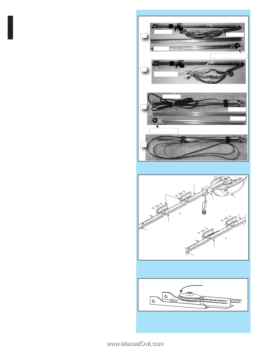
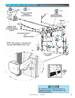
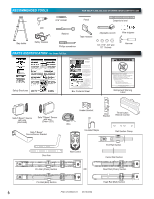
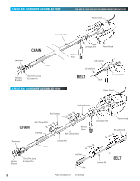
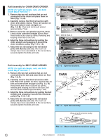
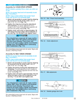
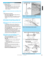
Rail Assembly for CHAIN DRIVE OPENER NOTE: For split rail clamps, nuts, and bolts locate Bag 0 from Box 1. 3. Remove the two rail sections that are not connected to the chain and place them on floor (Fig. 1-2, A). 4. Carefully remove the third rail section with chain and plastic sleeve. Place rail section on floor and extend chain straight out (Fig. 1-2, B). Chain and rail should extend approximately 7 feet. 5. Remove wire ties and plastic bag from chain. Leave chain extended straight out on floor. Avoid kinks in the chain by careful handling and keeping chain flat on the floor. 6. Align the three rail sections by pulling the chain straight and wrapping it around the chain tensioner pulley (Fig. 1-3 & 1-4). 7. Attach the two rail clamps to the rail section joints with (4) bolts and nuts. After both rail clamps have been assembled to the rail sections, securely tighten the bolts and nuts. CHAIN DRIVE RAILS Chain Rail A End Rail B Wire Tie(s) BELT DRIVE RAILS Belt Rail A Tensioner Pulley B Center Rail Chain Tensioner Pulley Center Rail End Rail Rail Assembly for BELT DRIVE OPENER NOTE: For split rail clamps, nuts, and bolts locate Bag 0 from Box 1. 3. Remove the two rail sections that are not connected to the belt and place them on floor (Fig. 1-2, A). 4. Carefully remove the third rail section with belt. Place rail section on floor, remove ties on belt and extend belt straight out (Fig. 1-2, B). Avoid twists and kinks in the belt by careful handling and keeping belt flat on the floor. Belt and rail should extend approximately 7 feet. 5. Align the three rail sections by pulling the belt straight and wrapping it around the tensioner pulley (Fig. 1-3 & 1-4). 6. Attach the two rail clamps to the rail section joints with (4) bolts and nuts. After both rail clamps have been assembled to the rail sections, securely tighten the bolts and nuts. FIG. 1-2 Split Rail sections. CHAIN Rail Clamps Rail with chain Rail Clamp Bolts End Rail HIGH SPRING TENSION RseCerpvaainciresCpoerarausdosjnuesutSsmineegrniptosroumpsuesrItntbojeoulmsryaandoderibnDystaerutarcattiihnoends dSmbooraomainnrceNusdintfdiraOsguotc.rcoTtCitubroiEsrounenntrtoseaf.reocotdr r Chain Release Knob Rail Clamp Nuts Center Rail ng End Rail HIGH SPRING TENSION RseCerpvaainciresCpoerarausdosjnuesutSsmineegrniptosroumpsuesrItntbojeoulmsryaandoderibnDystaerutarcattiihnoends dSmbooraomainnrceNusdintfdiraOsguotc.rcoTtCitubroiEsrounenntrtoseaf.reocotdr r Belt FIG. 1-3 Split Rail assembly. Carriage Slide Power Head Rail with belt Release Knob BELT Center Rail Wrap around tensioner pulley FIG. 1-4 Mount chain/belt to tensioner pulley. 10 PN# 37026500123 05/15/2009
-
 1
1 -
2
-
3
-
4
-
 5
5 -
 6
6 -
 7
7 -
 8
8 -
 9
9 -
 10
10 -
 11
11 -
 12
12 -
 13
13 -
 14
14 -
 15
15 -
16
-
17
-
18
-
19
-
20
-
21
-
22
-
23
-
24
-
25
-
26
-
27
-
28
-
29
-
30
 |
 |