Genie ChainLift 800 Owner's Manual - Page 17
Safe-t-beam, System Installation - instructions
 |
View all Genie ChainLift 800 manuals
Add to My Manuals
Save this manual to your list of manuals |
Page 17 highlights
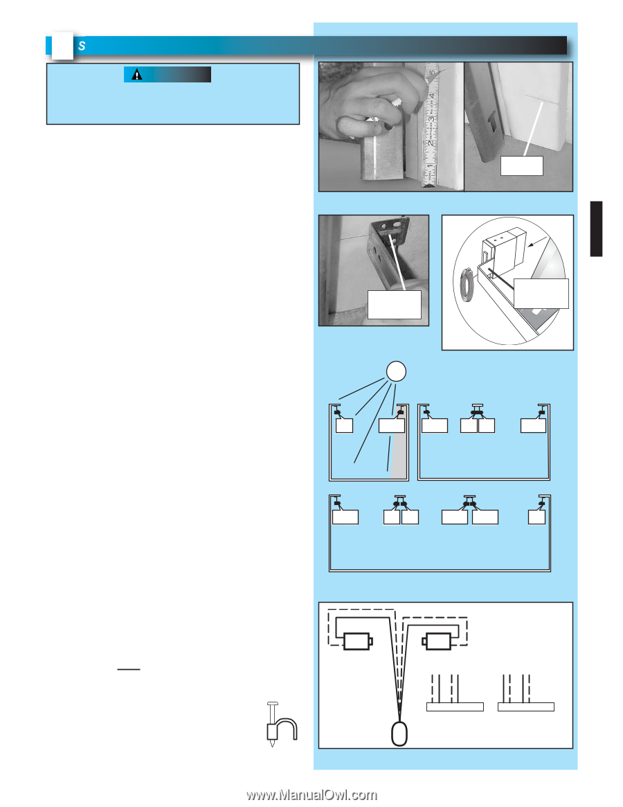
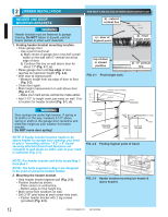
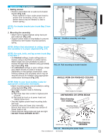
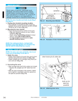
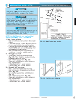
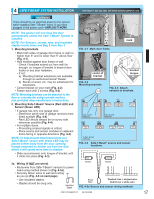
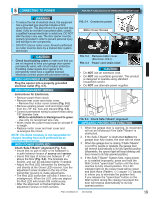
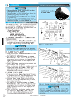
4 SAFE-T-BEAM® SYSTEM INSTALLATION FOR HELP-1.800.354.3643 OR WWW.GENIECOMPANY.COM WARNING There should be no electrical power to the opener while installing Safe-T-Beam® wires. If you have plugged in the power cord-UNPLUG IT NOW! NOTE: The opener will not close the door automatically unless the Safe-T-Beam® System is installed. NOTE: For Sensors, screws, wire, and insulated staples locate items and Bag 8 from Box 3. 1. Mounting brackets. • Mark both sides of garage door frame or wall no higher than 6" and no lower than 5" above floor (Fig. 4-1). • Hold bracket against door frame or wall. - Check if brackets extend out from wall far enough, so tongue of bracket is beyond door, tracks or any door hardware. - If not: a) Mounting bracket extensions are available through an authorized Genie® Dealer. b) Blocks of wood, etc. may be substituted for extensions. • Center bracket on your mark (Fig. 4-2). • Fasten each with 2 screws (Fig. 4-2). NOTE: Mounting brackets can be attached to the floor or concrete rim using concrete anchors (not provided) obey manufacturer's instructions. 2. Mounting Safe-T-Beam® Source (Red LED) and Sensor (Green LED). • If garage has only one garage door. - Determine which side of garage receives most direct sunlight (Fig. 4-4). - Red LED should always be on sunny side whenever possible (Fig. 4-4). • For multiple doors. - Preventing crossed signals is critical. - Place source and sensor modules on adjacent doors facing in opposite directions (Fig. 4-4). NOTE: To help prevent interference from sun, Safe-T-Beam® sensor with Green LED may be placed further away from the door opening, though extended no further out from the wall, where it will spend more time in shadow. • Slide source/sensor onto tongue of bracket until it clicks into place (Fig. 4-3). FIG. 4-1 Mark door frame. mark slide center of bracket FIG. 4-2 Mounting brackets. SUN bracket tongue FIG. 4-3 Attach sensors to brackets. RLEEDD GRLEEDEN GRLEEDEN RLEEDD RLEEDD GRLEEDEN ONE DOOR GARAGE TWO DOOR GARAGE GRLEEDEN RLEEDD RLEEDD GRLEEDEN GREEN LED RED LED THREE DOOR GARAGE FIG. 4-4 Safe-T-Beam® source and sensor locations. Red Green 3a. Wiring (If NOT pre-wired). • Route wire from Safe-T-Beam® sensors to power head using method shown in (Fig. 4-5a). • Securely fasten wires to wall and ceiling as you go (Fig. 4-6 on next page). - Use insulated staples. - Staples should be snug only. Insulated Staple Source Sensor 6 5 4 3 2 1 or 6 5 4 3 2 1 Power Head Dashed Line = striped wire Solid Line = white wire FIG. 4-5a Source and sensor wiring methods. PN# 37026500123 05/15/2009 17
-
 1
1 -
2
-
3
-
4
-
5
-
6
-
7
-
8
-
9
-
10
-
11
-
 12
12 -
 13
13 -
 14
14 -
 15
15 -
 16
16 -
 17
17 -
 18
18 -
 19
19 -
 20
20 -
 21
21 -
 22
22 -
23
-
24
-
25
-
26
-
27
-
28
-
29
-
30
 |
 |