Genie ChainLift 800 Owner's Manual - Page 18
Caution
 |
View all Genie ChainLift 800 manuals
Add to My Manuals
Save this manual to your list of manuals |
Page 18 highlights
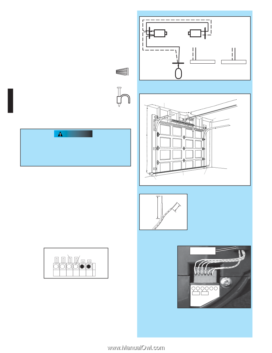
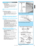
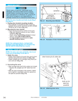
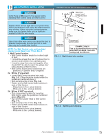
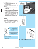
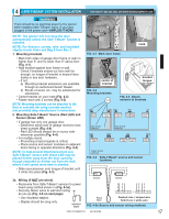
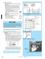
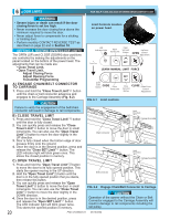
3b. Wiring (pre-wired). • Route wire from wall to Safe-T-Beam® sensors (Fig. 4-5b). • Splice pre-wiring to shortened sensor wire, match wire pairs dash-to-dash (striped-to- striped) and plain-to-plain (white-to-white). - Trim sensor wire to approximately one foot (1 ft) from sensor. - Split and strip ends of sensor wires and pre-wired wires (Fig. 4-7). - Splice wires together with (provided) wire nuts. • Route wire from ceiling to power head Wire Nut (Fig. 4-5b). • Securely fasten wires where they exit wall and ceiling as you go. - Use insulated staples. - Staples should be snug only. Insulated Staple Wall Red Source Wall Green Sensor Ceiling 6 5 4 3 2 1 or 6 5 4 3 2 1 Power Head Dashed Line = striped wire Solid Line = white wire FIG. 4-5b Pre-Wired source and sensor wiring methods. Insert Wire Wire Into Connector Wire CAUTION Staples which are too tight can cut or pinch wires. Cut or pinched wires can cause the Safe-T-Beam® System to stop working. When using the insulated staples, make sure you fasten them only as tightly as needed to hold the wire snugly. Use this wire routing if NOT pre-wired 4. Split and strip ends of sensor wires (Fig. 4-7). NOTE: For rear cover locate Box 4. 5. Attach Safe-T-Beam® wire to power head wire terminal. • Route Safe-T-Beam® wires through wire guide on power head. - Insert wire into terminal holes and lightly press in the orange locking clips above each terminal hole. (You can use a pencil or small screwdriver to comfortably reach in and lightly press down locking clips.) Insert white wires to 'even' numbered terminal holes and striped wires into 'odd' terminal holes (Fig. 4-8). Locking Clips Terminal Holes Sensor Invisible Light Beam Sensor Protection Area FIG. 4-6 Wire routing. 2" 1/2" FIG. 4-7 Splitting and stripping. wire guide 65 432 1 - Confirm wire lock by lightly tugging on the wire. The wire should remain in the terminal hole. • Do not install the white (lamp) cover at this time. NOTE: Safe-T-Beam® alignment check must be performed following connection to electrical power (see page 19). DO NOT PLUG IN YET! FIG. 4-8 Insert wires. 654 321 +- PB Infared Sensor (Power Head With Rear Cover Removed) 18 PN# 37026500123 05/15/2009
-
 1
1 -
2
-
3
-
4
-
5
-
6
-
7
-
8
-
9
-
10
-
11
-
12
-
 13
13 -
 14
14 -
 15
15 -
 16
16 -
 17
17 -
 18
18 -
 19
19 -
 20
20 -
 21
21 -
 22
22 -
 23
23 -
24
-
25
-
26
-
27
-
28
-
29
-
30
 |
 |