Gigabyte 7VM400AM-RZ User Manual
Gigabyte 7VM400AM-RZ Manual
 |
View all Gigabyte 7VM400AM-RZ manuals
Add to My Manuals
Save this manual to your list of manuals |
Gigabyte 7VM400AM-RZ manual content summary:
- Gigabyte 7VM400AM-RZ | User Manual - Page 1
7VM400AM-RZ AMD Athlon™/Athlon™ XP/Duron™ Socket A Processor Motherboard User's Manual Rev. 1003 12ME-VM400AMRZ-1003 Copyright © 2005 GIGABYTE TECHNOLOGY CO., LTD Copyright by GIGA-BYTE TECHNOLOGY CO., LTD. ("GBT"). No part of this manual may be reproduced or transmitted in any from without the - Gigabyte 7VM400AM-RZ | User Manual - Page 2
Mother Board 7VM400AM-RZ Oct. 7, 2004 Motherboard 7VM400AM-RZ Oct. 7 ,2004 - Gigabyte 7VM400AM-RZ | User Manual - Page 3
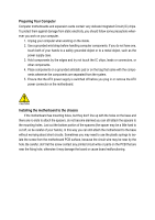
Preparing Your Computer Computer motherboards and expansion cards contain very delicate Integrated Circuit (IC) chips. To protect them against damage from static electricity, you should follow some precautions whenever you work on your computer. 1. Unplug your computer when working on the inside. 2. - Gigabyte 7VM400AM-RZ | User Manual - Page 4
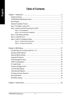
English Table of Contents Chapter 1 Introduction 5 Features Summary ...5 7VM400AM-RZ Motherboard Layout 7 Block Diagram ...8 Hardware Installation Process 9 Step 1: Set System Jumper (JP1 9 Step 2: Install the Central Processing Unit (CPU 10 Step 2-1: CPU Installation ...10 Step 2-2: - Gigabyte 7VM400AM-RZ | User Manual - Page 5
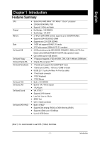
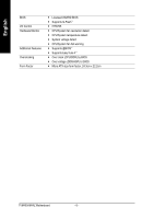
2/4/6-channel y Line Out / Line In / Mic In y SPDIF Out y CD In / Game connector y Built in VT8237 y Supports Disk striping (RAID0) or DISK Mirroring (RAID1) y Supports UDMA up to 150 MB/sec y Up to 2 SATA Device (Note 1) It is recommended to use SATA (1.5Gb/s) hard disks. - 5 - Introduction - Gigabyte 7VM400AM-RZ | User Manual - Page 6
/System fan revolution detect y CPU/System temperature detect y System voltage detect y CPU/System fan fail warning y Supports @BIOS™ y Supports EasyTune 4™ y Over clock (CPU/DDR) by BIOS y Over voltage (DDR/AGP) br BIOS y Micro ATX size form factor, 24.3cm x 22.2cm 7VM400AM-RZ Motherboard - 6 - - Gigabyte 7VM400AM-RZ | User Manual - Page 7
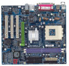
DDR2 IDE1 IDE2 24.3 cm 7VM400AM-RZ Motherboard Layout KB_MS USB 22.2 cm CPU_FAN ATX FDD COMA LPT VGA USB LAN MIC_IN LINE_OUT LINE_IN SOCKET A IT8705 VIA KM400A BIOS F_AUDIO AGP VT6103 - Gigabyte 7VM400AM-RZ | User Manual - Page 8
PCICLK (33MHz) USBCLK (48MHz) 14.318 MHz 33 MHz HCLK+/- (100/133/166/200MHz) CLK CPUCLK+/- (100/133/166/200MHz) GEN AGPCLK (66MHz) V_Link (66MHz) 7VM400AM-RZ Motherboard - 8 - - Gigabyte 7VM400AM-RZ | User Manual - Page 9
/200MHz by adjusting system jumper (JP1). (The internal frequency depend on CPU.) Short: 100MHz 1 Open: 133/166/200MHz 1 100MHz : Fix FSB 200MHz CPU 133/166MHz : Supports FSB 266/333MHz CPU If you want to use a CPU with 200MHz FSB, please set JP1 to 100MHz. JP1 - 9 - Hardware Installation Process - Gigabyte 7VM400AM-RZ | User Manual - Page 10
or grease) to provide better heat conduction between your CPU and cooling fan. Figure 2. Fasten the cooling fan supporting-base onto the CPU socket on the motherboard. Figure 3. Make sure the CPU fan is plugged to the CPU fan connector, than the install completely. 7VM400AM-RZ Motherboard - 10 - - Gigabyte 7VM400AM-RZ | User Manual - Page 11
English Step 3: Install Memory Modules Before installing the memory modules, adhere to the following warning: 1. Please note that the DIMM module can only fit in one direction due to the one notch. Wrong orientation will cause improper installation. Please change the insert orientation. The - Gigabyte 7VM400AM-RZ | User Manual - Page 12
Card 1. Read the relate AGP card's instruction document before install the AGP card into the a standard USB interface. Also make sure your OS supports USB controller. If your OS does not support USB controller, please contact OS vendor for possible patch Line In jack. 7VM400AM-RZ Motherboard - 12 - - Gigabyte 7VM400AM-RZ | User Manual - Page 13
English ` Line Out jack Connect the stereo speakers or earphone to this connector. a MIC In jack Microphone can be connect to MIC In jack. After installation of the audio driver, you are able to use 2/4/6-channel audio feature by software selection. You can connect "Front speaker" to "Line Out" - Gigabyte 7VM400AM-RZ | User Manual - Page 14
connector supports Max. current up to 600 mA. Pin No. Definition 1 1 GND 2 +12V 3 Sense 3) SYS_FAN (System Fan Connector) This connector allows you to link with the cooling fan on the system case to lower the system temperature. Pin No. Definition 1 1 GND 2 +12V 3 Sense 7VM400AM-RZ - Gigabyte 7VM400AM-RZ | User Manual - Page 15
English 4) FDD (Floppy Connector) Please connect the floppy drive ribbon cables to FDD. It supports 360K, 1.2M, 720K, 1.44M and 2.88M bytes floppy disk types. The red stripe of the ribbon cable must be the same side with the Pin1. - Gigabyte 7VM400AM-RZ | User Manual - Page 16
2- Pin 3: NC Pin 4: Data(-) Open: Normal Operation Close: Reset Hardware System Open: Normal Operation Close: Power On/Off Pin 1: LED anode(+) Pin 2: LED cathode(-) NC 7VM400AM-RZ Motherboard - 16 - - Gigabyte 7VM400AM-RZ | User Manual - Page 17
pin assigment on the cable is the same as the pin assigment on the MB header. To find out if the chassis you are buying support front audio connector, please contact your dealer. Please note, you can have the alternative of using front audio connector or of using rear audio connector - Gigabyte 7VM400AM-RZ | User Manual - Page 18
NRTSB- 8 NCTSB- 9 NRIB- 10 No Pin 14) GAME (Game Connector) This connector supports joystick, MIDI keyboard and other relate audio devices. Check the pin assignment while you connect the GPSB1 6 GRX2_R 14 MSO_R 7 GRY2_R 15 GPSB2 8 MSI_R 16 No Pin 7VM400AM-RZ Motherboard - 18 - - Gigabyte 7VM400AM-RZ | User Manual - Page 19
English 15) F_USB1 / F_USB2 (Front USB Connector) Be careful with the polarity of the front USB connector. Check the pin assignment carefully while you connect the front USB cable, incorrect connection between the cable and connector will make the device unable to work or even damage it. For - Gigabyte 7VM400AM-RZ | User Manual - Page 20
of used batteries according to the manufacturer's instructions. If you want to erase CMOS... 1. Turn OFF the computer and unplug the power cord. 2. Remove the battery, wait for 30 second. 3. Re-install the battery. 4. Plug the power cord and turn ON the computer. 7VM400AM-RZ Motherboard - 20 - - Gigabyte 7VM400AM-RZ | User Manual - Page 21
English Chapter 2 BIOS Setup BIOS Setup is an ov erv iew of the BIOS Setup Program. The program that allow s users to modify the basic sy stem configuration. This ty pe of information is stored in battery -backed CM OS RAM so that it retains the Setup information w hen the pow er is turned off. - Gigabyte 7VM400AM-RZ | User Manual - Page 22
& Exit S etup Sav e CMOS v alue settings to CMOS and ex it s etup. • Exit Without S aving Abandon all CM OS v alue changes and ex it s etup. 7VM400AM-RZ Motherboard - 22 - - Gigabyte 7VM400AM-RZ | User Manual - Page 23
IDE dev ices are used and the sy stem w ill skip the automatic detec tion step and allow for faster sy s tem start up. Manual User can manually input the correct settings IDE C hannel 2/ 3 Master IDE Dev ic e Setup. You can use one of tw o methods: Auto Allow s BIOS to automatic ally - Gigabyte 7VM400AM-RZ | User Manual - Page 24
e; 1.44M by te capacity . 2.88M, 3.5" 3.5 inch double-sided driv e; 2.88M by te capacity . Floppy 3 Mode Support (for Japan Area) Disa bled Normal Floppy Driv e. (Default v alue) Driv e A Driv e A is 3 mode Floppy abov e 1 MB in the CPU 's memory address map. 7VM400AM-RZ Motherboard - 24 - - Gigabyte 7VM400AM-RZ | User Manual - Page 25
English Advanced BIOS Features CMOS Setup Ut ility-Co pyright (C) 1984 -2004 Aw ard Soft ware Adva nced BI OS Feat ures } Hard Disk Bo ot Prio rity First Boot De vice Secon d Boot D evice Third Boot De vice Pass word C heck [Press Enter] [Flo ppy] [Hard Disk] [CDR OM] [Set up] Item Help Menu L - Gigabyte 7VM400AM-RZ | User Manual - Page 26
port. OnChip Serial ATA Enab led Enable onboard VT8237 Serial ATA support. (Default v alue) Disa bled Disabled VT8237 Serial ATA support. SATA Mode RAID IDE Selec t SATA chip function as RAID. Disable this function if y ou are not using the onboard USB feature. 7VM400AM-RZ Motherboard - 26 - - Gigabyte 7VM400AM-RZ | User Manual - Page 27
alue) Disable USB 2. 0 controller. USB Keyboard Support Enab led Enable USB key board support. Disa bled Disable USB key board support. (Default v alue) USB Mouse Support Enab led Enable USB mouse support. Disa bled Disable USB m ouse support. (Default v alue) Onboard Serial P ort 1 Auto - Gigabyte 7VM400AM-RZ | User Manual - Page 28
on y our sy stem. Mouse P ower On Disa bled Enab led Disabled this function. (Default v alue) Pow er on sy stem by mouse ev ent. 7VM400AM-RZ Motherboard - 28 - - Gigabyte 7VM400AM-RZ | User Manual - Page 29
English PME Event Wake Up When set at Enabled, any PCI-PM ev ent can aw ak e the sy stem from a PCI-PM controlled stated. This feature requires an ATX pow er supply that prov ides at least 1A on the +5VSB lead. Disa bled Disable this function. Enab led Enable PME as w ake up ev ent. (Default - Gigabyte 7VM400AM-RZ | User Manual - Page 30
v alue) Enab led Fan w arning function enable. SYSTEM FAN Fail Warning Disa bled Fan w arning function disable. (Default v alue) Enab led Fan w arning function enable. 7VM400AM-RZ Motherboard - 30 - - Gigabyte 7VM400AM-RZ | User Manual - Page 31
English Frequency/Voltage Control CMOS Setup Ut ility-Co pyright (C) 1984 -2004 Aw ard Soft ware Frequ ency/Vol tage Con trol Auto Detect PCI/DIMM Clk Spre ad Spec turm CPU Host Cl ock Con trol x CPU C lock DRAM Clock( MHz) AGP OverVolt age Con trol DIMM OverVol tage Con trol [Enab led] [Enab - Gigabyte 7VM400AM-RZ | User Manual - Page 32
S etup Load Optimiz ed Defa ults Selecting this field loads the factory defaults for BIOS and Chipset Features w hich the sy stem automatically dete cts. 7VM400AM-RZ Motherboard - 32 - - Gigabyte 7VM400AM-RZ | User Manual - Page 33
English Set Supervisor/User Password CMOS Setup Ut ility-Co pyright (C) 1984 -2004 Aw ard Soft ware } Stan dard CM OS Feat ures } Adva nced BI OS Feat ures } Inte grated Periphe rals } Powe r Manag ement S etup } PnP/ PCI Con figuratEinotnesr Passw ord: } PC H ealth St atus } Frequ ency/Vol tage - Gigabyte 7VM400AM-RZ | User Manual - Page 34
S etup Aban don all Data Ty pe "Y" w ill quit the Setup Utility w ithout sav ing to RTC CMOS. Ty pe "N" w ill return to Setup Utility . 7VM400AM-RZ Motherboard - 34 - - Gigabyte 7VM400AM-RZ | User Manual - Page 35
CD-ROM drive, the driver CD-title will auto start and show the installation guide. If not, please double click the CD-ROM device icon in "My be installed for the system. Click each item to install the driver manually or switch to the to install the drivers automatically. The "Xpress Install - Gigabyte 7VM400AM-RZ | User Manual - Page 36
please use Windows Service Pack. After install Windows Service Pack, it will show a question mark "?" in "Universal Serial Bus controller" under "Device Manager". Please remove the question mark and restart the system (System will auto-detect the right USB2.0 driver). 7VM400AM-RZ Motherboard - 36 - Gigabyte 7VM400AM-RZ | User Manual - Page 37
- 37 - Driver Installation English - Gigabyte 7VM400AM-RZ | User Manual - Page 38
English 7VM400AM-RZ Motherboard - 38 - - Gigabyte 7VM400AM-RZ | User Manual - Page 39
Bletchley Milton Keynes, MK1 1DR, UK, England TEL: +44-1908-362700 FAX: +44-1908-362709 Tech. Support : http://uk.giga-byte.com/TechSupport/ServiceCenter.htm Non-Tech. Support(Sales/Marketing) : http://ggts.gigabyte.com.tw/nontech.asp WEB address : http://uk.giga-byte.com - The Netherlands GIGA-BYTE - Gigabyte 7VM400AM-RZ | User Manual - Page 40
://www.gigabyte.ru - Poland Representative Office Of Giga-Byte Technology Co., Ltd. POLAND Tech. Support : http://tw.giga-byte.com/TechSupport/ServiceCenter.htm Non-Tech. Support(Sales/Marketing) : http://ggts.gigabyte.com.tw/nontech.asp WEB address : http://www.gigabyte.pl 7VM400AM-RZ Motherboard
-
 1
1 -
 2
2 -
 3
3 -
 4
4 -
 5
5 -
 6
6 -
 7
7 -
8
-
9
-
10
-
11
-
12
-
13
-
14
-
15
-
16
-
17
-
18
-
19
-
20
-
21
-
22
-
23
-
24
-
25
-
26
-
27
-
28
-
29
-
30
-
31
-
32
-
33
-
34
-
35
-
36
-
37
-
38
-
39
-
40
 |
 |

7VM400AM-RZ
User's Manual
Rev. 1003
12ME-VM400AMRZ-1003
Copyright
© 2005 GIGABYTE TECHNOLOGY CO., LTD
Copyright by
GIGA-BYTE TECHNOLOGY CO., LTD.
("GBT").
No part of this manual may
be reproduced or transmitted in
any from without the expressed, written permission of
GBT
.
T
rademarks
Third-party brands and names are the property of their respective owners.
Notice
Please do not remove any labels on motherboard, this may void the warranty of this motherboard.
Due to rapid change in technology, some of the specifications might be out of date before publication of this booklet.
The author assumes no responsibility for any errors or omissions that may appear in this document nor does the author make
a commitment to update the information contained herein.
AMD Athlon
™
/Athlon
™
XP/Duron
™
Socket A Processor Motherboard