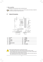
Gigabyte GA-78LMT-S2PV Manual - Page 14
F_PANEL Front Panel Header, F_AUDIO Front Panel Audio Header
 |
View all Gigabyte GA-78LMT-S2PV manuals
Add to My Manuals
Save this manual to your list of manuals |
Page 14 highlights
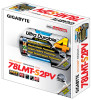
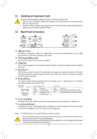
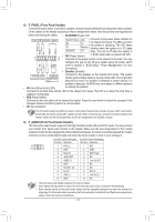
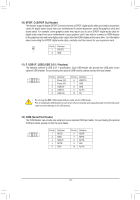
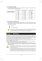
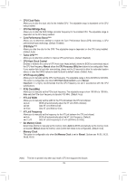
8) F_PANEL (Front Panel Header) Connect the power switch, reset switch, speaker, chassis intrusion switch/sensor and system status indicator on the chassis to this header according to the pin assignments below. Note the positive and negative pins before connecting the cables. •• PLED/PWR Power LED: PLED+ PLED- PW+ PWSPEAK+ SPEAK- Power LED Power Switch Speaker System Status LED S0 On S1 Blinking S3/S4/S5 Off Connects to the power status indicator on the chassis front panel. The LED is on when the system is operating. The LED keeps blinking when the system is in S1 sleep state. The LED is off when the system is F_PANEL(NH) 2 1 20 19 •• PW (Power Switch): in S3/S4 sleep state or powered off (S5). PWM Switch (SW1)(X79-UD7) ConnFe_PcAtsNEtLo the power switch on the chassis front panel. You may confi(gHu61reM-Dth2e) way to turn off your system using the power switch DIP 12345 HD+ HD- RESRES+ CICI+ PWR+ PWRPWR- (refer to Chapter 2, "BIOS Setup," "Power Management," for more information). •• Speaker (Speaker): Hard Drive Activity LED Reset Switch Power LED Chassis Intrusion Header Connects to the speaker on the chassis front panel. The system reports system startup status by issuing a beep code. One single short beep will be heard if no problem is detected at system startup. If a problem is detected, the BIOS may issue beeps in different patterns •• HD (Hard Drive Activity LED): to indicate the problem. BIOS Switcher (X58A-OC) Connects to the hard drive activity LED on the chassis front panel. The LED is on when the hard drive is reading or writing data. 1 •• RES (Reset Switch): M_SACToAnnects to the reset switch on the chassis front panel. Press the reset switch to restart the computer if the computer freezes and fails to perform a normal restart. •• NC: No connection. PWM Switch (X58A-OC) The front panel design may differ by chaA(GsCsAPi-sII_V.CABP)fTront panel module mainly consists of poweB(GrIOAsS-wIV_iPtBcH)h, reset switch, power LED, hard drive activity LED, speaker and etc. When connecting your chassis front panel module to this header, make sure the wire assignments and the pin assignments are matched correctly. DIP 1 23 1 DIP 1 23 1 DIP 1 23 1 9) DIP 1 23 PCIe Control (Z87X-UP7) F_AUDIO (Front Panel Audio Header) The front panel audio header supports Intel High Definition audio (HD) and AC'97 audio. You may connect your chassis front panel audio module toSMthBi_sCPhTeader. Make sure the wire assignments of the module connector match the pin assignments of the(GmA-oIVthB)erboard header. Incorrect connection between the module connector and the motherboard header will make the device unable to work or even damage it. For HD Front Panel Audio: For AC'97 Front Panel Audio: Pin No. Definition Pin No. Definition 9 1 10 2 1 MIC2_LCLR_CMOS 1 MIC 2 GND CI 2 GND 3 MIC2_RDGIPS1_5M_ECPT 3 MIC Power 4 -ACZ_D(EGTA-IVB) 4 NC 5 LINE2_R 5 Line Out (R) ATX_12V_2X3 6 GND 6 NC XDP_CPU 7 FAUDIOX_DJPD_PCH 7 NC 8 No Pin (GA-IVB) 8 No Pin 9 LINE2_L 9 Line Out (L) 10 GND 10 NC •• The front panel audio header supF_pUoSrtBs3H(FDroanut dPiaonbely) default. •• Audio signals will be present on both of the front and back panel audio connections simultaneously. •• Some chassis provide a front panel audio module that has separated connectors on each wire instead of a single plug. For information about connecting the front panel audio module that has different wire assignments, please contact the chassis manufacturer. - 14 -
-
 1
1 -
2
-
3
-
4
-
5
-
6
-
7
-
8
-
 9
9 -
 10
10 -
 11
11 -
 12
12 -
 13
13 -
 14
14 -
 15
15 -
 16
16 -
 17
17 -
 18
18 -
 19
19 -
20
-
21
-
22
-
23
-
24
-
25
-
26
-
27
-
28
-
29
-
30
-
31
-
32
-
33
-
34
-
35
-
36
 |
 |