Gigabyte GA-78LMT-S2PV Manual - Page 16
BIOS Setup
 |
View all Gigabyte GA-78LMT-S2PV manuals
Add to My Manuals
Save this manual to your list of manuals |
Page 16 highlights
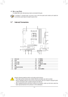
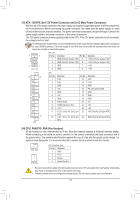
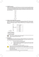
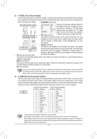
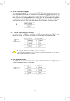
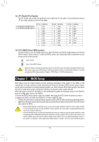
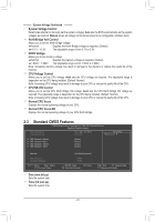
13) LPT (Parallel Port Header) The LPT header can provide one parallel port via an optional LPT port cable. For purchasing the optional LPT port cable, please contact the local dealer. Pin No. Definition Pin No. Definition Pin No. Definition 25 1 1 STB- 10 GND 19 ACK- 26 2 2 AFD- 11 PD4 20 GND 3 PD0 12 GND 21 BUSY 4 ERR- 13 PD5 22 GND 5 PD1 14 GND 23 PE 6 INIT- 15 PD6 24 No Pin 7 PD2 16 GND 25 SLCT 8 SLIN- 17 PD7 26 GND 9 PD3 18 GND 14) CLR_CMOS (Clear CMOS Jumper) Use this jumper to clear the CMOS values (e.g. date information and BIOS configurations) and reset the CMOS values to factory defaults. To clear the CMOS values, use a metal object like a screwdriver to touch the two pins for a few seconds. Open: Normal Short: Clear CMOS Values •• Always turn off your computer and unplug the power cord from the power outlet before clearing the CMOS values. •• After system restart, go to BIOS Setup to load factory defaults (select Load Optimized Defaults) or manually configure the BIOS settings (refer to Chapter 2, "BIOS Setup," for BIOS configurations). Chapter 2 BIOS Setup BIOS (Basic Input and Output System) records hardware parameters of the system in the CMOS on the motherboard. Its major functions include conducting the Power-On Self-Test (POST) during system startup, saving system parameters and loading operating system, etc. BIOS includes a BIOS Setup program that allows the user to modify basic system configuration settings or to activate certain system features. When the power is turned off, the battery on the motherboard supplies the necessary power to the CMOS to keep the configuration values in the CMOS. To access the BIOS Setup program, press the key during the POST when the power is turned on. To upgrade the BIOS, use either the GIGABYTE Q-Flash or @BIOS utility. •• Q-Flash allows the user to quickly and easily upgrade or back up BIOS without entering the operating system. •• @BIOS is a Windows-based utility that searches and downloads the latest version of BIOS from the Internet and updates the BIOS. •• Because BIOS flashing is potentially risky, if you do not encounter problems using the current version of BIOS, it is recommended that you not flash the BIOS. To flash the BIOS, do it with caution. Inadequate BIOS flashing may result in system malfunction. •• It is recommended that you not alter the default settings (unless you need to) to prevent system instability or other unexpected results. Inadequately altering the settings may result in system's failure to boot. If this occurs, try to clear the CMOS values and reset the board to default values. (Refer to the "Load Optimized Defaults" section in this chapter or introductions of the battery/clear CMOS jumper in Chapter 1 for how to clear the CMOS values.) - 16 -
-
 1
1 -
2
-
3
-
4
-
5
-
6
-
7
-
8
-
9
-
10
-
 11
11 -
 12
12 -
 13
13 -
 14
14 -
 15
15 -
 16
16 -
 17
17 -
 18
18 -
 19
19 -
 20
20 -
 21
21 -
22
-
23
-
24
-
25
-
26
-
27
-
28
-
29
-
30
-
31
-
32
-
33
-
34
-
35
-
36
 |
 |
