Gigabyte GA-7PXSL1 Manual - Page 27
F_AUDIO Front Panel Audio Header, TPM_1 TPM Module Connector
 |
View all Gigabyte GA-7PXSL1 manuals
Add to My Manuals
Save this manual to your list of manuals |
Page 27 highlights
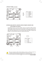
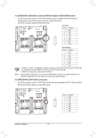
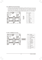
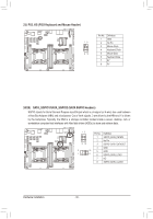
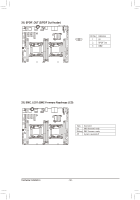
18) F_AUDIO (Front Panel Audio Header) The front panel audio header supports Intel High Definition audio (HD) and AC'97 audio. You may connect your chassis front panel audio module to this header. Make sure the wire assignments of the module connector match the pin assignments of the motherboard header. Incorrect connection between the module connector and the motherboard header will make the device unable to work or even damage it. A E K R Y AB 1 5 10 15 20 22 1 Pin No. Definition 1 MIC_L 2 GND 10 9 3 MIC_R 4 5V 5 LINE_R 6 MIC_Detect 21 7 GND 8 No Pin 9 LINE_L 10 LINE_Detect Y AB R K E A 20 22 15 10 5 1 19) TPM_1 (TPM Module Connector) 1 2 1 Pin No. Definition 1 CLK_33M_TPM 2 P_3V3_AUX 3 LPC_RST_DEBUG 14 4 P3V3 13 5 LPC_LAD0 6 IRQ_SERIAL 7 LPC_LAD1 8 TPM_DET_N 9 LPC_LAD2 10 NC 11 LPC_LAD3 12 GND 13 LPC_FRAME_N 14 GND - 27 - Hardware Installation
-
 1
1 -
2
-
3
-
4
-
5
-
6
-
7
-
8
-
9
-
10
-
11
-
12
-
13
-
14
-
15
-
16
-
17
-
18
-
19
-
20
-
21
-
 22
22 -
 23
23 -
 24
24 -
 25
25 -
 26
26 -
 27
27 -
 28
28 -
 29
29 -
 30
30 -
 31
31 -
 32
32 -
33
-
34
-
35
-
36
-
37
-
38
-
39
-
40
-
41
-
42
-
43
-
44
-
45
-
46
-
47
-
48
-
49
-
50
-
51
-
52
-
53
-
54
-
55
-
56
-
57
-
58
-
59
-
60
-
61
-
62
-
63
-
64
-
65
-
66
-
67
-
68
-
69
-
70
-
71
-
72
-
73
-
74
-
75
-
76
-
77
-
78
-
79
-
80
-
81
-
82
-
83
-
84
-
85
-
86
-
87
-
88
-
89
-
90
-
91
-
92
-
93
-
94
-
95
-
96
-
97
 |
 |
