Gigabyte GA-8IPE775-G Manual - Page 17
Step 2: Installation of Memory - manual
 |
View all Gigabyte GA-8IPE775-G manuals
Add to My Manuals
Save this manual to your list of manuals |
Page 17 highlights
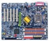
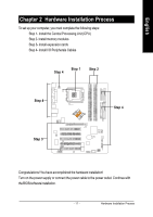
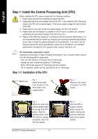
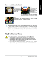
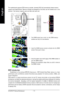
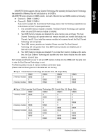
English Step 1-2: Installation of the Heatsink Fig.1 Please apply an even layer of heatsink paste on the surface of the installed CPU. Fig. 2 Place the heatsink atop the CPU and then secure each of the four heatsink clips by pressing downwards. (for detailed installation instructions, please refer to the heat sink installation section of the user manual) Fig. 3 Please attach the power connector of the heatsink to the CPU fan header located on the motherboard. Installation is complete. The heatsink may adhere to the CPU as a result of hardening of the heatsink paste. If the heatsink is removed when this occurs, the CPU may become pulled from its socket with the metal lever still in its locked position and result in damage to the processor pins. To prevent such an occurrence, it is suggested that either thermal tape rather than heat sink paste be used for heat dissipation or using extreme care when removing the heatsink. Step 2: Installation of Memory Before installing the memory modules, please comply with the following conditions: 1. Please make sure that the memory used is supported by the motherboard. It is recommended that memory of similar capacity, specifications and brand be used. 2. Before installing or removing memory modules, please make sure that the computer power is switched off to prevent hardware damage. 3. Memory modules have a foolproof insertion design. A memory module can be installed in only one direction. If you are unable to insert the module, please switch the direction. - 13 - Hardware Installation Process
-
 1
1 -
2
-
3
-
4
-
5
-
6
-
7
-
8
-
9
-
10
-
11
-
 12
12 -
 13
13 -
 14
14 -
 15
15 -
 16
16 -
 17
17 -
 18
18 -
 19
19 -
 20
20 -
 21
21 -
 22
22 -
23
-
24
-
25
-
26
-
27
-
28
-
29
-
30
-
31
-
32
-
33
-
34
-
35
-
36
-
37
-
38
-
39
-
40
-
41
-
42
-
43
-
44
-
45
-
46
-
47
-
48
-
49
-
50
-
51
-
52
-
53
-
54
-
55
-
56
-
57
-
58
-
59
-
60
-
61
-
62
-
63
-
64
-
65
-
66
-
67
-
68
-
69
-
70
-
71
-
72
-
73
-
74
-
75
-
76
-
77
-
78
-
79
-
80
-
81
-
82
-
83
-
84
-
85
-
86
-
87
-
88
-
89
-
90
-
91
-
92
-
93
-
94
-
95
-
96
 |
 |
