Gigabyte GA-8IPE775-G Manual - Page 30
IR_CIR, F_USB1 / F_USB2 Front USB Connector
 |
View all Gigabyte GA-8IPE775-G manuals
Add to My Manuals
Save this manual to your list of manuals |
Page 30 highlights
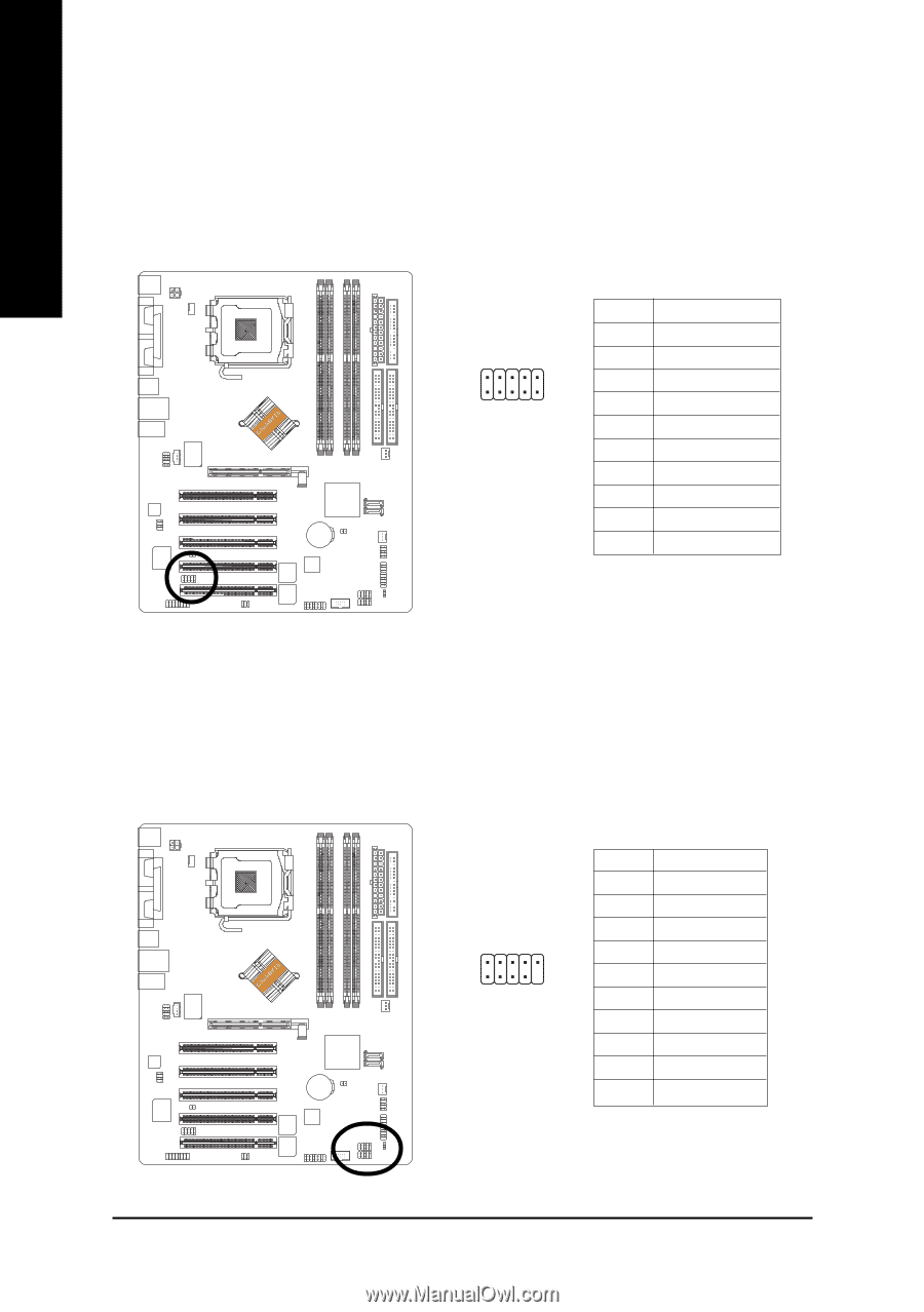
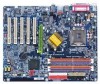
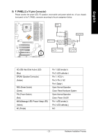
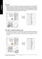
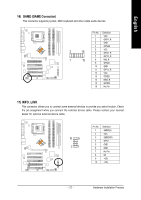
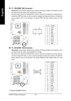
English 14) IR_CIR Make sure the pin 1 on the IR device is aling with pin one the connector. To enable the IR/CIR function on the board, you are required to purchase an option IR/CIR module. To use IR function only, please connect IR module to Pin1 to Pin5. Be careful with the polarity of the IR/CIR connector. Check the pin assignment carefully while you connect the IR/CIR cable, incorrect connection between the cable and connector will make the device unable to work or even damage it. For optional IR/CIR cable, please contact your local dealer. 6 10 15 Pin No. 1 2 3 4 5 6 7 8 9 10 Definition VCC NC IRRX GND IRTX NC CIRRX +5VSB CIRTX NC 15) F_USB1 / F_USB2 (Front USB Connector) Be careful with the polarity of the front USB connector. Check the pin assignment carefully while you connect the front USB cable, incorrect connection between the cable and connector will make the device unable to work or even damage it. For optional front USB cable, please contact your local dealer. 2 10 19 Pin No. 1 2 3 4 5 6 7 8 9 10 Definition Power Power USB DxUSB DyUSB Dx+ USB Dy+ GND GND No Pin NC GA-8IPE775 Series Motherboard - 26 -
-
 1
1 -
2
-
3
-
4
-
5
-
6
-
7
-
8
-
9
-
10
-
11
-
12
-
13
-
14
-
15
-
16
-
17
-
18
-
19
-
20
-
21
-
22
-
23
-
24
-
 25
25 -
 26
26 -
 27
27 -
 28
28 -
 29
29 -
 30
30 -
 31
31 -
 32
32 -
 33
33 -
 34
34 -
 35
35 -
36
-
37
-
38
-
39
-
40
-
41
-
42
-
43
-
44
-
45
-
46
-
47
-
48
-
49
-
50
-
51
-
52
-
53
-
54
-
55
-
56
-
57
-
58
-
59
-
60
-
61
-
62
-
63
-
64
-
65
-
66
-
67
-
68
-
69
-
70
-
71
-
72
-
73
-
74
-
75
-
76
-
77
-
78
-
79
-
80
-
81
-
82
-
83
-
84
-
85
-
86
-
87
-
88
-
89
-
90
-
91
-
92
-
93
-
94
-
95
-
96
 |
 |