Gigabyte GA-990FX-Gaming Manual - Page 12
Onboard Buttons and Switch, 1-8 Changing the Operational Amplifier
 |
View all Gigabyte GA-990FX-Gaming manuals
Add to My Manuals
Save this manual to your list of manuals |
Page 12 highlights
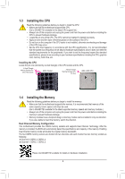
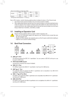
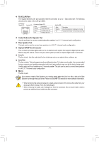
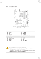
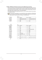
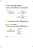
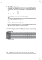
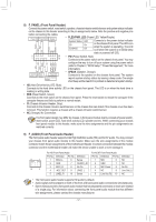
B SS 1 23 1 1 1-7 Onboard Buttons and Switch _S 1 23 1 1 23 1 Quick Buttons This motherboard has 3 quick buttons: power button, reset button and clear CMOS b_utton. The power button BS and reset button allow users to quickly turn on/off or reset the computer in an open-cBase environment when they wanSt to change hardware components or conduct hardware testing. Use this button to clear the BIOS configuration and reset the CMOS values to factory defaults when needed. S B SS S PW_SW: Power Button RST_SW: Reset Button 1 23 CMOS_SW: Clear CMOS Button S B_ B •• Always turn off your computer and unplug the power cord from the power outlet before clearing the CMOS values. •• NOTE: Do not use the clear CMOS button when the system is on, or the system may shutdown and data loss or damage may occur. •• After system restart, go to BIOS Setup to load factory defaults (select Loa_dSOptimized Defaults) or manually configure the BIOS settings (refer to Chapter 2, "BIOS Setup," for BIOS configurations). S_ Audio Gain Control Switch _ B This switch allows for audio gain control for the line-out jack on the back panel. Please make sure all of the dips are set in the same position and are set according to your headphone specification (actual effects may vary by the device being used). _U U _ _ _DIP Se3tting Gain Ratio DIP 1 DIP 2 DIP 3 DIP 4 B 2.5x OFF OFF OFF OFF 6x ON ON ON ON F_USB3 F SF 1-8 Changing the Operational Amplifier _ Step 1: Use an IC extractor to carefully grip the IC's sides and extract it from the socket. _ _B B_ _ Step 2: Align the notch on your OP chip with the notch on the socket and gently press the chip into the socket until seated. For purchasing the IC extractor and OP Chip, please contact the local dealer. - 12 -
-
 1
1 -
2
-
3
-
4
-
5
-
6
-
 7
7 -
 8
8 -
 9
9 -
 10
10 -
 11
11 -
 12
12 -
 13
13 -
 14
14 -
 15
15 -
 16
16 -
 17
17 -
18
-
19
-
20
-
21
-
22
-
23
-
24
-
25
-
26
-
27
-
28
-
29
-
30
-
31
-
32
-
33
-
34
-
35
-
36
-
37
-
38
-
39
-
40
-
41
-
42
-
43
-
44
 |
 |
