Gigabyte GA-990FX-Gaming Manual - Page 19
COMA Serial Port Header, BAT Battery, TPM Trusted Platform Module Header
 |
View all Gigabyte GA-990FX-Gaming manuals
Add to My Manuals
Save this manual to your list of manuals |
Page 19 highlights
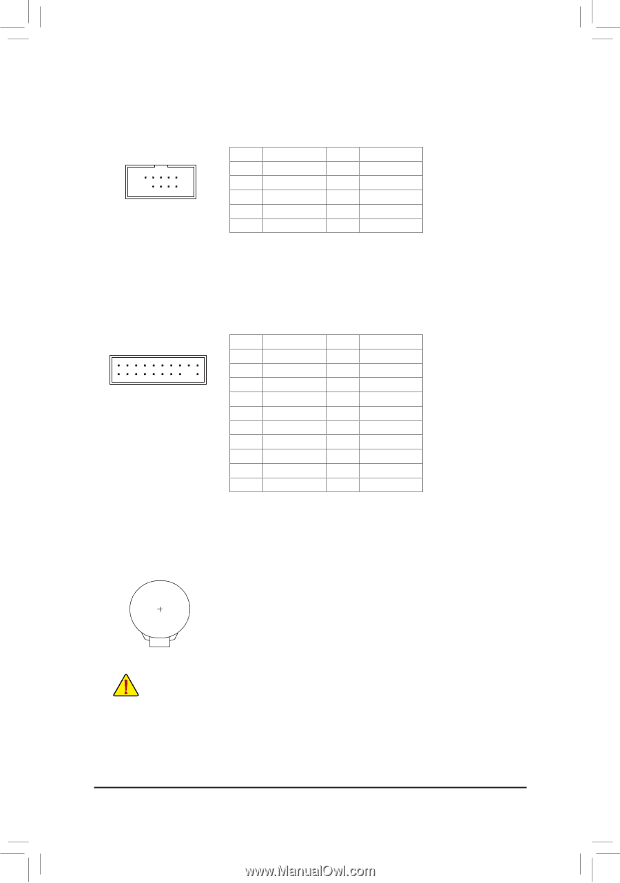
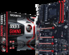
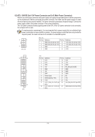
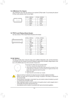
13) COMA (Serial Port Header) The COM header can provide one serial port via an optional COM port cable. For purchasing the optional COM port cable, please contact the local dealer. F_USB30 F_ U F_ Pin No. Definition Pin No. Definition 1 NDCD- 6 NDSR- 9 10 1 2 2 NSIN 7 NRTS- 3 NSOUT 8 NCTS- 4 NDTR- 9 NRI- 5 GND 10 No Pin 1 23 1 B SS B_ 14) TPM (Trusted Platform Module Header) 1 You may connect a TPM (Trusted Platform Module) to this header. _S 1 23 1 1 23 1 Pin No. Definition Pin No. Definition 19 1 1 LCLK 11 LAD0 2 GND 12 GND S 20 2 3 LFRAME 13 NC 4 No Pin 14 NC 5 LRESET 6 NC S 7 LAD3 15 SB3V 1 2 3 16 SERIRQ 17 GND 8 LAD2 18 NC 9 VCC3 19 NC 10 LAD1 20 SUSCLK 15) BAT (Battery) The battery provides power to keep the values (such as BIOS configurations, date, and time information) in the CMOS when the computer is turned off. Replace the battery when the battery voltage drops to a low level, or the CMOS values may not be accurate or may be lost. S3 B SS S U You may clear the CMOS values by removing the battery: __ 1. Turn off your computer and unplug the power cord. 2. Gently remove the battery from the battery holder and wait for one minute. (Or use a metal object like a screwdriver to touch the positive and negative terminals of the battery holder, making them short for 5 seconds.) S_ 3. Replace the battery. 4. Plug in the power cSordFand restart your computer._ •• Always turn off your computer and unplug the power cord before replacing the battery. •• Replace the battery with an equivalent one. Danger of explosion if the battery is replaced with an incorrect model. •• Contact the place of purchase or local dealer if you are not able to replace the battery by yourself or uncertain about the battery model. •• When installing the battery, noteBt_he orientation of the positive s_ide (+) and the negative side (-) of the battery (the positive side should face up). •• Used batteries must be handled in accordance with local environmental regulations. 3 _ _B S_ - 19 -
-
 1
1 -
2
-
3
-
4
-
5
-
6
-
7
-
8
-
9
-
10
-
11
-
12
-
13
-
 14
14 -
 15
15 -
 16
16 -
 17
17 -
 18
18 -
 19
19 -
 20
20 -
 21
21 -
 22
22 -
 23
23 -
 24
24 -
25
-
26
-
27
-
28
-
29
-
30
-
31
-
32
-
33
-
34
-
35
-
36
-
37
-
38
-
39
-
40
-
41
-
42
-
43
-
44
 |
 |