Gigabyte GA-G41M-Combo Manual - Page 33
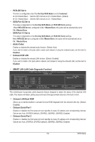
SMART LAN LAN Cable Diagnostic Function
 |
View all Gigabyte GA-G41M-Combo manuals
Add to My Manuals
Save this manual to your list of manuals |
Page 33 highlights
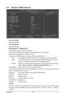
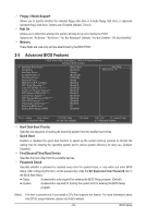
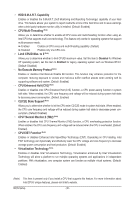
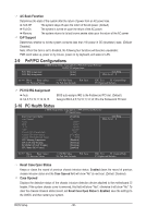
PATA IDE Set to This item is configurable only if the On-Chip SATA Mode is set to Combined. Ch.0 Master/Slave Sets the IDE channels to Ch. 0 Master/Slave. (Default) Ch.1 Master/Slave Sets the IDE channels to Ch. 1 Master/Slave. SATA Port 0/2 Set to This value is dependent on the On-Chip SATA Mode and PATA IDE Set to settings. When PATA IDE Set to is configured to Ch. 1 Master/Slave, this option will be automatically set to Ch. 0 Master/Slave. SATA Port 1/3 Set to This value is dependent on the On-Chip SATA Mode and PATA IDE Set to settings. When PATA IDE Set to is configured to Ch. 0 Master/Slave, this option will be automatically set to Ch. 1 Master/Slave. Azalia Codec Enables or disables the onboard audio function. (Default: Auto) If you wish to install a 3rd party add-in audio card instead of using the onboard audio, set this item to Disabled. Onboard H/W LAN Enables or disables the onboard LAN function. (Default: Enabled) If you wish to install a 3rd party add-in network card instead of using the onboard LAN, set this item to Disabled. SMART LAN (LAN Cable Diagnostic Function) CMOS Setup Utility-Copyright (C) 1984-2010 Award Software SMART LAN Start detecting at Port..... Part1-2 Status = Open / Length = 0m Part3-6 Status = Open / Length = 0m Part4-5 Status = Open / Length = 0m Part7-8 Status = Open / Length = 0m Item Help Menu Level Move Enter: Select F5: Previous Values +/-/PU/PD: Value F10: Save F6: Fail-Safe Defaults ESC: Exit F1: General Help F7: Optimized Defaults This motherboard incorporates cable diagnostic feature designed to detect the status of the attached LAN cable. This feature will detect cabling issue and report the approximate distance to the fault or short. Onboard LAN Boot ROM Allows you to decide whether to activate the boot ROM integrated with the onboard LAN chip. (Default: Disabled) Onboard Serial Port 1 Enables or disables the first serial port and specifies its base I/O address and corresponding interrupt. Options are: Auto, 3F8/IRQ4 (default), 2F8/IRQ3, 3E8/IRQ4, 2E8/IRQ3, Disabled. Onboard Serial Port 2 Enables or disables the first serial port and specifies its base I/O address and corresponding interrupt. Options are: Auto, 3F8/IRQ4, 2F8/IRQ3 (default), 3E8/IRQ4, 2E8/IRQ3, Disabled. - 33 - BIOS Setup
-
 1
1 -
2
-
3
-
4
-
5
-
6
-
7
-
8
-
9
-
10
-
11
-
12
-
13
-
14
-
15
-
16
-
17
-
18
-
19
-
20
-
21
-
22
-
23
-
24
-
25
-
26
-
27
-
 28
28 -
 29
29 -
 30
30 -
 31
31 -
 32
32 -
 33
33 -
 34
34 -
 35
35 -
 36
36 -
 37
37 -
 38
38 -
39
-
40
-
41
-
42
-
43
-
44
 |
 |