Gigabyte GA-K8VT800 User Manual - Page 25
F_ USB1 / F_USB2 Front USB Connector
 |
View all Gigabyte GA-K8VT800 manuals
Add to My Manuals
Save this manual to your list of manuals |
Page 25 highlights
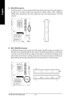
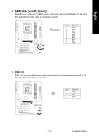
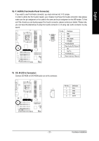
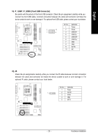
English 14) F_ USB1 / F_USB2 (Front USB Connector) Be careful with the polarity of the front USB connector. Check the pin assignment carefully while you connect the front USB cable, incorrect connection between the cable and connector will make the device unable to work or even damage it. For optional front USB cable, please contact your local dealer. Pin No. Definition 1 Power 2 10 2 Power 1 9 3 USB DX- 4 USB Dy- 5 USB DX+ 6 USB Dy+ 7 GND 8 GND 9 No Pin 10 NC 15) IR Check the pin assignments carefully while you connect the IR cable because incorrect connection between the cable and connector will make the device unable to work or even damage it. For optional IR cable, please contact your local dealer. Pin No. Definition 1 Power 1 2 No Pin 3 IR RX 4 GND 5 IR TX - 25 - Hardware Installation
-
 1
1 -
2
-
3
-
4
-
5
-
6
-
7
-
8
-
9
-
10
-
11
-
12
-
13
-
14
-
15
-
16
-
17
-
18
-
19
-
 20
20 -
 21
21 -
 22
22 -
 23
23 -
 24
24 -
 25
25 -
 26
26 -
 27
27 -
 28
28 -
 29
29 -
 30
30 -
31
-
32
-
33
-
34
-
35
-
36
-
37
-
38
-
39
-
40
-
41
-
42
-
43
-
44
-
45
-
46
-
47
-
48
-
49
-
50
-
51
-
52
-
53
-
54
-
55
-
56
-
57
-
58
-
59
-
60
-
61
-
62
-
63
-
64
-
65
-
66
-
67
-
68
-
69
-
70
-
71
-
72
-
73
-
74
-
75
-
76
-
77
-
78
-
79
-
80
 |
 |
