Gigabyte GA-Q57M-S2H Manual - Page 30
LPT Parallel Port Header, DEBUG PORT Debug Card Header, debug card cable
 |
View all Gigabyte GA-Q57M-S2H manuals
Add to My Manuals
Save this manual to your list of manuals |
Page 30 highlights
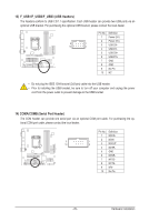
15) LPT (Parallel Port Header) The LPT header can provide one parallel port via an optional LPT port cable. For purchasing the optional LPT port cable, please contact the local dealer. 25 1 24 Pin No. 1 2 3 4 5 6 7 8 9 10 11 12 13 Definition STBAFDPD0 ERRPD1 INITPD2 SLINPD3 GND PD4 GND PD5 2 Pin No. 14 15 16 17 18 19 20 21 22 23 24 25 26 Definition GND PD6 GND PD7 GND ACKGND BUSY GND PE No Pin SLCT GND 16) DEBUG PORT (Debug Card Header) The header can connect one debug card via an optional debug card cable. For purchasing the optional debug card cable, please contact the local dealer. 11 1 12 2 Pin No. 1 2 3 4 5 6 7 8 9 10 11 12 Definition No Pin GND VCC3 LAD0 LAD1 LAD2 LAD3 -LFRAME -PFMRST DB CLK DB_P_SENSOR NC Hardware Installation - 30 -
-
 1
1 -
2
-
3
-
4
-
5
-
6
-
7
-
8
-
9
-
10
-
11
-
12
-
13
-
14
-
15
-
16
-
17
-
18
-
19
-
20
-
21
-
22
-
23
-
24
-
 25
25 -
 26
26 -
 27
27 -
 28
28 -
 29
29 -
 30
30 -
 31
31 -
 32
32 -
 33
33 -
 34
34 -
 35
35 -
36
-
37
-
38
-
39
-
40
-
41
-
42
-
43
-
44
-
45
-
46
-
47
-
48
-
49
-
50
-
51
-
52
-
53
-
54
-
55
-
56
-
57
-
58
-
59
-
60
-
61
-
62
-
63
-
64
-
65
-
66
-
67
-
68
-
69
-
70
-
71
-
72
-
73
-
74
-
75
-
76
-
77
-
78
-
79
-
80
-
81
-
82
-
83
-
84
-
85
-
86
-
87
-
88
-
89
-
90
-
91
-
92
-
93
-
94
-
95
-
96
-
97
-
98
-
99
-
100
-
101
-
102
-
103
-
104
-
105
-
106
-
107
-
108
-
109
-
110
-
111
-
112
 |
 |
