Gigabyte GA-Z87X-UD4H User Manual - Page 27
CPU_FAN/SYS_FAN1/SYS_FAN2/SYS_FAN3/SYS_FAN4 Fan Headers, CPU_OPT Water Cooling CPU Fan Header
 |
View all Gigabyte GA-Z87X-UD4H manuals
Add to My Manuals
Save this manual to your list of manuals |
Page 27 highlights
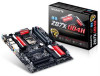
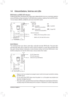
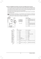
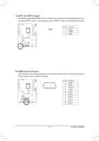
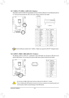
5/6) CPU_FAN/SYS_FAN1/SYS_FAN2/SYS_FAN3/SYS_FAN4 (Fan Headers) The motherboard has a 4-pin CPU fan header (CPU_FAN), three 4-pin (SYS_FAN1~SYS_FAN3) and a 3-pin (SYS_FAN4) system fan headers. Most fan headers possess a foolproof insertion design. When con- necting a fan cable, be sure to connect it in the correct orientation (the black connector wire is the ground wire). The speed control function requires the use of a fan with fan speed control design. For optimum heat dissipation, it is recommended that a system fan be installed inside the chassis. CPU_FAN: Pin No. Definition 1 CPU_FAN 1 GND 2 +12V 3 Sense 4 Speed Control 1 SYS_FAN1 1 SYS_FAN2 1 SYS_FAN3 1 SYS_FAN4 SYS_FAN1/SYS_FAN2/SYS_FAN3: Pin No. Definition 1 GND 2 +12V /Speed Control 3 Sense 4 VCC SYS_FAN4: Pin No. Definition 1 GND 2 +12V 3 NC 7) CPU_OPT (Water Cooling CPU Fan Header) The fan header is 4-pin and possesses a foolproof insertion design. When connecting a fan cable, be sure to connect it in the correct orientation (the black connector wire is the ground wire). The speed control function requires the use of a fan with fan speed control design. Pin No. Definition 1 GND 1 2 +12V /Speed Control 3 Sense 4 VCC •• Be sure to connect fan cables to the fan headers to prevent your CPU and system from overheating. Overheating may result in damage to the CPU or the system may hang. •• These fan headers are not configuration jumper blocks. Do not place a jumper cap on the headers. - 27 - Hardware Installation
-
 1
1 -
2
-
3
-
4
-
5
-
6
-
7
-
8
-
9
-
10
-
11
-
12
-
13
-
14
-
15
-
16
-
17
-
18
-
19
-
20
-
21
-
 22
22 -
 23
23 -
 24
24 -
 25
25 -
 26
26 -
 27
27 -
 28
28 -
 29
29 -
 30
30 -
 31
31 -
 32
32 -
33
-
34
-
35
-
36
-
37
-
38
-
39
-
40
-
41
-
42
-
43
-
44
-
45
-
46
-
47
-
48
-
49
-
50
-
51
-
52
-
53
-
54
-
55
-
56
-
57
-
58
-
59
-
60
-
61
-
62
-
63
-
64
-
65
-
66
-
67
-
68
-
69
-
70
-
71
-
72
-
73
-
74
-
75
-
76
-
77
-
78
-
79
-
80
-
81
-
82
-
83
-
84
-
85
-
86
-
87
-
88
-
89
-
90
-
91
-
92
-
93
-
94
-
95
-
96
-
97
-
98
-
99
-
100
-
101
-
102
-
103
-
104
-
105
-
106
-
107
-
108
-
109
-
110
-
111
-
112
-
113
-
114
-
115
-
116
-
117
-
118
-
119
-
120
-
121
-
122
-
123
-
124
 |
 |
