Gigabyte GA-Z87X-UD4H User Manual - Page 32
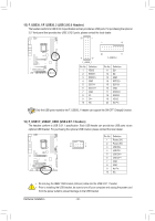
F_USB1/F_USB2/F_USB3 USB 2.0/1.1 Headers, F_USB30_1/F_USB30_2 USB 3.0/2.0 Headers
 |
View all Gigabyte GA-Z87X-UD4H manuals
Add to My Manuals
Save this manual to your list of manuals |
Page 32 highlights
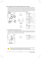
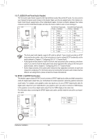
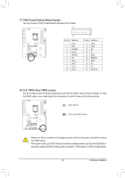
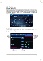
DIP 1 234 DIP 1 23 1 F_USB30 F_AUDIO(H) F 15) F_USB30_1/F_USB30_2 (USB 3.0/2.0 Headers) The headers conform to USB 3.0/2.0 specification and can provide two USB ports. For purchasing the optional 3.5" front panel that provides two USB 3.0/2.0 ports, please contact the local dealer. 20 1 1 10 F_USB30 DB_PORT F_BAIOUSDISOw(Hitc)her (X58A-OC) DIP 1 23 1 20 11 1 11 10 F_USB30_2 DIP 1 23 1 TPM w/housing F_USB30_1 Pin No. 1 2 DefinGi.tioQnBOFM Pin No. Definition VBUS Voltage me1a1suremenDt2m+odule(X58A-OC) SSRX1- 12 D2- PWM Switch (X58A-OC) 3 SSRX1+ 13 GND 4 GND 5 SSTX1- 14 SSTX2+ 15 SSTX2- DB_PORTDIP 1 23 6 SSTX1+ PCIe p1ow6er conGneNctDor (SATA)(X58A-OC) 7 GND 17 SSRX2+ 8 D1- 18 SSRX2- 9 D1+ 10 TNPCM w/housing 19 VBUS 20 No Pin Voltage measurement module(X5 Only the USB ports routed to the F_USB30_1 header can support the ON/OFF Charge2 function. 16) F_USB1/F_USB2/F_USB3 (USB 2.0/1.1 Headers) PCIe power connector (SATA The headers conform to USB 2.0/1.1 speVocltiafigceamtioeans.urEemacenht pUoSintBs(Gh1e.Sandipeerr 3c)an provide BtwIOoS USwSitBchepro(SrtWs4v) ia an PCIe Control (Z87X-UP7 optional USB bracket. For purchasing the optional USB bracket, please contact the local dealer. DIP 1 234 DIP 1 234 9 1 10 2 Pin No. Definition 1 Power (5V) 2 Power (5V) 3 USB DX4 USB DY5 USB DX+ Voltage6measurUeSmBenDt pYo+ints(G1.Sniper 3) 7 GND 8 GND 9 No Pin 10 NC DIP 1 234 BIOS Switcher ( •• Do not plug the IEEE 1394 bracket (2x5-pin) cable into the USB 2.0/1.1 header. •• Prior to installing the USB bracket, be sure to turn off your computer and unplug the power cord from the power outlet to prevent damage to the USB bracket. Hardware Installation - 32 -
-
 1
1 -
2
-
3
-
4
-
5
-
6
-
7
-
8
-
9
-
10
-
11
-
12
-
13
-
14
-
15
-
16
-
17
-
18
-
19
-
20
-
21
-
22
-
23
-
24
-
25
-
26
-
 27
27 -
 28
28 -
 29
29 -
 30
30 -
 31
31 -
 32
32 -
 33
33 -
 34
34 -
 35
35 -
 36
36 -
 37
37 -
38
-
39
-
40
-
41
-
42
-
43
-
44
-
45
-
46
-
47
-
48
-
49
-
50
-
51
-
52
-
53
-
54
-
55
-
56
-
57
-
58
-
59
-
60
-
61
-
62
-
63
-
64
-
65
-
66
-
67
-
68
-
69
-
70
-
71
-
72
-
73
-
74
-
75
-
76
-
77
-
78
-
79
-
80
-
81
-
82
-
83
-
84
-
85
-
86
-
87
-
88
-
89
-
90
-
91
-
92
-
93
-
94
-
95
-
96
-
97
-
98
-
99
-
100
-
101
-
102
-
103
-
104
-
105
-
106
-
107
-
108
-
109
-
110
-
111
-
112
-
113
-
114
-
115
-
116
-
117
-
118
-
119
-
120
-
121
-
122
-
123
-
124
 |
 |
