Gigabyte MD50-LS0 Manual - Page 7
Intel LGA2011 Socket R Primary CPU
 |
View all Gigabyte MD50-LS0 manuals
Add to My Manuals
Save this manual to your list of manuals |
Page 7 highlights
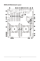
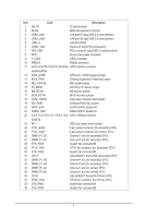
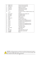
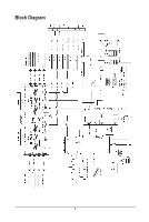
Item Code Description 1 SW_ID 2 MLAN 3 USB3_LAN1 4 USB3_LAN2 ID switch button BMC Management LAN port LAN port #1 (top)/USB 3.0 ports (bottom) LAN port #2 (top)/USB 3.0 ports (bottom) 5 LAN3_4 LAN port #3/#4 6 COM1_VGA Serial port (top)/VGA port(buttom) 7 PS2_USB PS/2 connector (top)/USB 2.0 ports (buttom) 8 ATX1 24 pin main power connector 9 F_USB3 USB 3.0 header 10 PMBUS PMBus connector 11 SATA0/SATA1/SATA2/SATA3/ SATA 3 6Gb/s connector SATA4/SATA5 12 SATA_DOM1 SATA port 1 DOM support jumper 13 BIOS_PWD Clearing Supervisor Password jumper 14 ME_UPDATE 15 S3_MASK 16 ME_RCVR ME update jumper S3 Power On Select jumper ME recovry jumper 17 BIOS_RCVR BIOS recovery jumper 18 CASE_OPEN Case open intrusion alert header 19 SW_RAID Software RAID Key jumper 20 SATA_SGP sSATA SGPIO header #2 21 SSATA_SGP sSATA SGPIO header #1 22 S S ATA 0 / S S ATA 1 / S S ATA 2 / SATA 3 6Gb/s connector SSATA3 23 BP_1 HDD back plane board header 24 P12V_AUX2 8 pin power connector (for secondary CPU) 25 P12V_AUX1 8 pin power connector (for primary CPU) 26 DIMM_P1_E0 27 DIMM_P1_F0 28 SYS_FAN5 29 CPU1_FAN Channel 1 slot (for secondary CPU) Channel 2 slot (for secondary CPU) System fan connector#5 CPU1 fan connector (for Secondary CPU) 30 SYS_FAN4 System fan connector#4 31 CPU1 Intel LGA2011 Socket R3 (Secondary CPU) 32 DIMM_P1_H0 Channel 4 slot (for secondary CPU) 33 DIMM_P1_G0 Channel 3 slot (for secondary CPU) 34 DIMM_P0_A0 Channel 1 slot (for primary CPU) 35 DIMM_P0_B0 Channel 2 slot (for primary CPU) 36 CPU0 Intel LGA2011 Socket R (Primary CPU) 37 CPU0_FAN CPU0 fan connector (for Primary CPU) 38 SYS_FAN3 System fan connector#3 39 SYS_FAN2 System fan connector#2 - 7 -
-
 1
1 -
 2
2 -
 3
3 -
 4
4 -
 5
5 -
 6
6 -
 7
7 -
 8
8 -
 9
9 -
 10
10 -
 11
11 -
 12
12 -
13
-
14
-
15
-
16
-
17
-
18
-
19
-
20
-
21
-
22
-
23
-
24
-
25
-
26
-
27
-
28
-
29
-
30
-
31
-
32
-
33
-
34
-
35
-
36
-
37
-
38
-
39
-
40
-
41
-
42
-
43
-
44
-
45
-
46
-
47
-
48
-
49
-
50
-
51
-
52
-
53
-
54
-
55
-
56
-
57
-
58
-
59
-
60
-
61
-
62
-
63
-
64
-
65
-
66
-
67
-
68
-
69
-
70
-
71
-
72
-
73
-
74
-
75
-
76
-
77
-
78
-
79
-
80
-
81
-
82
-
83
-
84
-
85
-
86
-
87
-
88
-
89
-
90
-
91
-
92
-
93
-
94
-
95
-
96
-
97
-
98
-
99
-
100
-
101
-
102
-
103
-
104
-
105
-
106
-
107
-
108
-
109
-
110
-
111
-
112
-
113
-
114
-
115
-
116
-
117
-
118
-
119
-
120
-
121
-
122
-
123
-
124
 |
 |