Gigabyte MD50-LS0 Manual - Page 8
Force to Stop FRB Timer jumper
 |
View all Gigabyte MD50-LS0 manuals
Add to My Manuals
Save this manual to your list of manuals |
Page 8 highlights
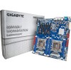
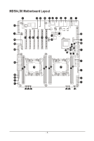
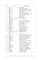
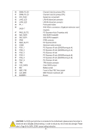
40 DIMM_P0_D0 41 DIMM_P0_C0 42 SYS_FAN1 43 LAN3_LED 44 LAN4_LED 45 FP_1 46 SAS0~7 47 RAID_SLOT2 48 SAS_SGP2 49 SAS_SGP1 50 IPMB 51 RAID_SLOT1 52 COM2 53 PCIE_1 54 PCIE_2 55 PCIE_3 56 PCIE_4 57 PCIE_5 58 PCIE_6 59 TPM 60 CLR_CMOS 61 BAT 62 BMC_FRB 63 LED_BMC 64 BUZZER1 Channel 4 slot (for primary CPU) Channel 3 slot (for primary CPU) System fan connector#1 LAN #3 Active/Link connector LAN #4 Active/Link connector Front panel header SAS 6Gb/s connectors (Gigabyte extension card required) PCI Express x4 slot (Proprietary slot) SAS SGPIO header#2 SAS SGPIO header#1 IPMB connector PCI Express x8 slot Serial port cable connector PCI Express x16 slot (GEN3/Running at x4) PCI Express x16 slot (GEN3/Running at x4) PCI Express x16 slot PCI Express x16 slot (GEN3/Running at x8) PCI Express x16 slot (GEN3/Running at x8) PCI Express x16 slot TPM module connector Clear CMOS jumper Battery socket Force to Stop FRB Timer jumper BMC firmware readiness LED Buzzer CAUTION! If a SATA type hard drive is connected to the motherboard, please ensure the jumper is closed and set to 2-3 pins (Default setting), in order to reduce any risk of hard disk damage. Please refer to Page 34 for SATA_DOM1 jumper setting instruction. - 8 -
-
 1
1 -
2
-
 3
3 -
 4
4 -
 5
5 -
 6
6 -
 7
7 -
 8
8 -
 9
9 -
 10
10 -
 11
11 -
 12
12 -
 13
13 -
14
-
15
-
16
-
17
-
18
-
19
-
20
-
21
-
22
-
23
-
24
-
25
-
26
-
27
-
28
-
29
-
30
-
31
-
32
-
33
-
34
-
35
-
36
-
37
-
38
-
39
-
40
-
41
-
42
-
43
-
44
-
45
-
46
-
47
-
48
-
49
-
50
-
51
-
52
-
53
-
54
-
55
-
56
-
57
-
58
-
59
-
60
-
61
-
62
-
63
-
64
-
65
-
66
-
67
-
68
-
69
-
70
-
71
-
72
-
73
-
74
-
75
-
76
-
77
-
78
-
79
-
80
-
81
-
82
-
83
-
84
-
85
-
86
-
87
-
88
-
89
-
90
-
91
-
92
-
93
-
94
-
95
-
96
-
97
-
98
-
99
-
100
-
101
-
102
-
103
-
104
-
105
-
106
-
107
-
108
-
109
-
110
-
111
-
112
-
113
-
114
-
115
-
116
-
117
-
118
-
119
-
120
-
121
-
122
-
123
-
124
 |
 |
