Gigabyte MH70-HD0 Manual - Page 27
FP_1 Front Panel Header, F_USB3 USB 3.0 Header
 |
View all Gigabyte MH70-HD0 manuals
Add to My Manuals
Save this manual to your list of manuals |
Page 27 highlights
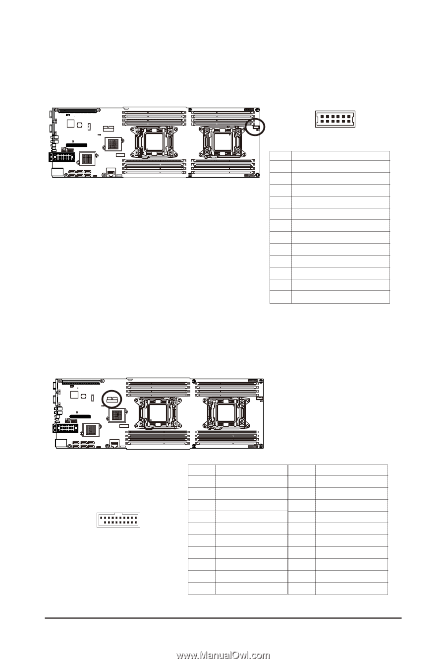
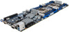
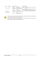
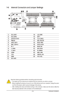
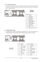
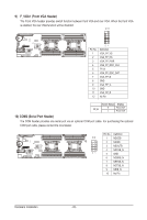
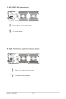
7) FP_1 (Front Panel Header) Connect the power switch, reset switch, chassis intrusion switch/sensor and system status indicator on the chassis to this header according to the pin assignments below. Note the positive and negative pins before connecting the cables. 11 1 12 2 Pin No. 1 2 3 4 5 6 7 8 9 10 11 12 Definition PS_ON_N I2C_FCB_SCL PSU_PWRGD I2C_FCB_SDA BMC_FCB_N STATUS_GREEN_N FP_PWR_BTN_N STATUS_AMBER_N ACK_BMC_N BMC_UID_LED_N GND BMC_UID_BUTTON_TTL_N 8) F_USB3 (USB 3.0 Header) The headers conform to USB 3.0 specification. Each USB header can provide two USB ports via an optional USB bracket. For purchasing the optional USB bracket, please contact the local dealer. 1 10 20 11 Pin No. 1 2 3 4 5 6 7 8 9 10 Definition Power IntA_P1_SSRXIntA_P1_SSRX+ GND IntA_P1_SSTXIntA_P1_SSTX+ GND IntA_P1_DIntA_P1_D+ NC Pin No. 11 12 13 14 15 16 17 18 19 20 Definition IntA_P2_D+ IntA_P2_DGND IntA_P2_SSTX+ IntA_P2_SSTXGND IntA_P2_SSRX+ IntA_P2_SSRXPower No Pin - 27 - Hardware Installation
-
 1
1 -
2
-
3
-
4
-
5
-
6
-
7
-
8
-
9
-
10
-
11
-
12
-
13
-
14
-
15
-
16
-
17
-
18
-
19
-
20
-
21
-
 22
22 -
 23
23 -
 24
24 -
 25
25 -
 26
26 -
 27
27 -
 28
28 -
 29
29 -
 30
30 -
 31
31 -
 32
32 -
33
-
34
-
35
-
36
-
37
-
38
-
39
-
40
-
41
-
42
-
43
-
44
-
45
-
46
-
47
-
48
-
49
-
50
-
51
-
52
-
53
-
54
-
55
-
56
-
57
-
58
-
59
-
60
-
61
-
62
-
63
-
64
-
65
-
66
-
67
-
68
-
69
-
70
-
71
-
72
-
73
-
74
-
75
-
76
-
77
-
78
-
79
-
80
-
81
-
82
-
83
-
84
-
85
-
86
-
87
-
88
-
89
-
90
-
91
-
92
-
93
-
94
-
95
-
96
-
97
-
98
-
99
-
100
-
101
-
102
-
103
-
104
-
105
-
106
-
107
-
108
-
109
-
110
-
111
-
112
-
113
-
114
 |
 |