Gigabyte MH70-HD0 Manual - Page 6
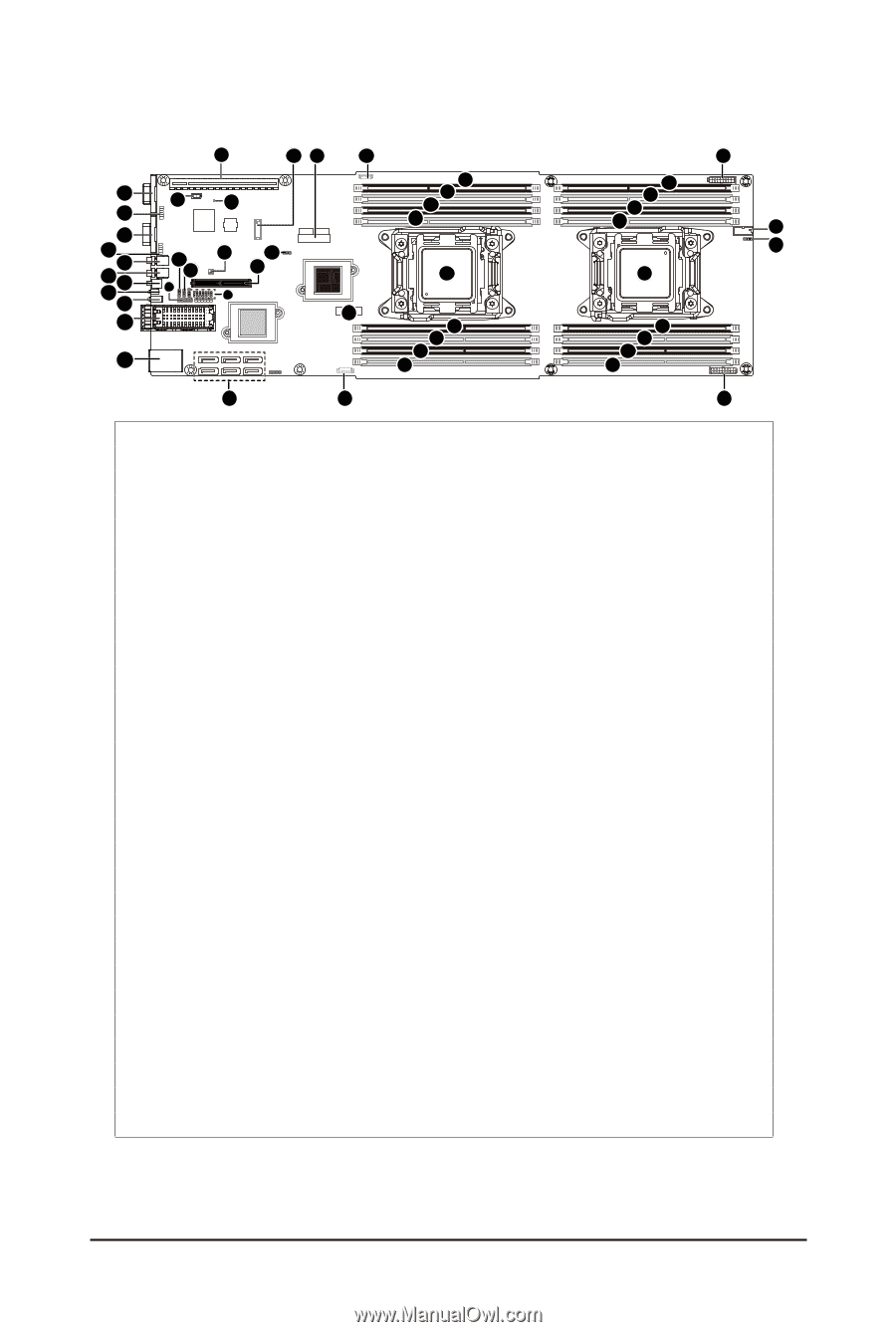
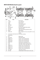
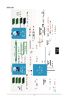
MH70-HD0 Motherboard Layout
 |
View all Gigabyte MH70-HD0 manuals
Add to My Manuals
Save this manual to your list of manuals |
Page 6 highlights
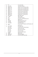
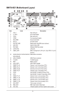
MH70-HD0 Motherboard Layout 1 2 3 4 5 6 8 7 9 10 11 40 41 42 39 38 37 33 34 35 36 48 49 43 44 45 47 45 19 13 18 17 16 15 28 29 30 31 32 27 26 20 21 22 23 24 12 14 25 Item Code Description 1 VGA_1 Rear VGA port 2 F_VGA1 Front VGA header 3 COM1 Rear serial port 4 COM2 5 SW_PWR1 6 SW_ID 7 SW_RST_NMI Front serial port header Power button/LED ID switch button Reset button (top)/NMI button (buttom) 8 LED_STA System status LED 9 LED_LAN LAN1 (buttom)/LAN2 (top) Active/Link LEDs 10 QSFP_1 QSFP LAN port 11 USB3_LAN1 BMC management LAN port (top)/USB 3.0 ports (buttom) 12 SATA0/SATA1/SATA2/SATA3/ SATA 6Gb/s connectors SATA4/SATA5 13 BAT1 Battery socket 14 SATA_SGP1 SATA SGPIO header 15 DIMM_P0_A0 Channel 1 slot 0 (for primary CPU) 16 DIMM_P0_A1 Channel 1 slot 1 (for primary CPU) 17 DIMM_P0_B0 18 DIMM_P0_B1 19 CPU0 Channel 2 slot 0 (for primary CPU) Channel 2 slot 1 (for primary CPU) Intel LGA2011 Socket R (Primary CPU) 20 CPU1 Intel LGA2011 Socket R (Secondary CPU) 21 DIMM_P1_H1 Channel 4 slot 1 (for secondary CPU) 22 DIMM_P1_H0 Channel 4 slot 0 (for secondary CPU) 23 DIMM_P1_G1 Channel 3 slot 1 (for secondary CPU) 24 DIMM_P1_G0 Channel 3 slot 0 (for secondary CPU) 25 SSI_2X9P1 18 pin power connector 26 ACK_SEL 4 Nodes System and Rack System switch jumper - 6 -
-
 1
1 -
 2
2 -
 3
3 -
 4
4 -
 5
5 -
 6
6 -
 7
7 -
 8
8 -
 9
9 -
 10
10 -
 11
11 -
 12
12 -
13
-
14
-
15
-
16
-
17
-
18
-
19
-
20
-
21
-
22
-
23
-
24
-
25
-
26
-
27
-
28
-
29
-
30
-
31
-
32
-
33
-
34
-
35
-
36
-
37
-
38
-
39
-
40
-
41
-
42
-
43
-
44
-
45
-
46
-
47
-
48
-
49
-
50
-
51
-
52
-
53
-
54
-
55
-
56
-
57
-
58
-
59
-
60
-
61
-
62
-
63
-
64
-
65
-
66
-
67
-
68
-
69
-
70
-
71
-
72
-
73
-
74
-
75
-
76
-
77
-
78
-
79
-
80
-
81
-
82
-
83
-
84
-
85
-
86
-
87
-
88
-
89
-
90
-
91
-
92
-
93
-
94
-
95
-
96
-
97
-
98
-
99
-
100
-
101
-
102
-
103
-
104
-
105
-
106
-
107
-
108
-
109
-
110
-
111
-
112
-
113
-
114
 |
 |