Gigabyte MNIC8CI Manual - Page 15
F_AUDIO Front Panel Audio Header, JRS1 RS232/RS422/RS485 Select Header
 |
View all Gigabyte MNIC8CI manuals
Add to My Manuals
Save this manual to your list of manuals |
Page 15 highlights
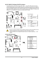
2) F_AUDIO (Front Panel Audio Header) The front panel audio header supports Intel High Definition audio (HD) and AC'97 audio. You may connect your chassis front panel audio module to this header. Make sure the wire assignments of the module connector match the pin assignments of the motherboard header. Incorrect connection between the module connector and the motherboard header will make the device unable to work or even damage it. 2 1 12 11 Pin No. 1 2 3 4 5 6 7 8 9 10 11 12 Definition Amplifier Out_R+ MIC_L Amplifier Out_RMIC_R GND Line In_R Amplifier Out_L+ Line In_L Amplifier Out_LLine In_JD GND External MIC JD 3) JRS1 (RS232/RS422/RS485 Select Header) 1 5 2 6 Pin No. 1 2 3 4 Definition RS232 UART RXD Signal RS422 UART RXD Signal 5 RS485 6 UART RXD Signal - 15 - Hardware Installation
-
 1
1 -
2
-
3
-
4
-
5
-
6
-
7
-
8
-
9
-
 10
10 -
 11
11 -
 12
12 -
 13
13 -
 14
14 -
 15
15 -
 16
16 -
 17
17 -
 18
18 -
 19
19 -
 20
20 -
21
-
22
-
23
-
24
-
25
-
26
-
27
 |
 |
