Gigabyte MNIC8CI Manual - Page 21
/18 F_USB3/F_USB2/F_USB1 USB Headers
 |
View all Gigabyte MNIC8CI manuals
Add to My Manuals
Save this manual to your list of manuals |
Page 21 highlights
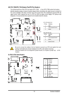
16/17/18) F_USB3/F_USB2/F_USB1 (USB Headers) The headers conform to USB 2.0/1.1 specification. Each USB header can provide two USB ports via an optional USB bracket. For purchasing the optional USB bracket, please contact the local dealer. F_USB1 F_USB2 1 2 9 10 F_USB3 F_USB1/F_USB2 Pin No. 1 2 3 4 5 6 7 8 9 10 Definition Power (5V) Power (5V) USB DXUSB DYUSB DX+ USB DY+ GND GND No Pin NC F_USB3 Pin No. 1 2 3 4 5 6 7 8 9 10 Definition Power (5V) Power (5V) USB DXNC USB DX+ NC GND GND No Pin NC When the system is in S4/S5 mode, only the USB ports routed to the F_USB1 header can support the ON/OFF Charge function. Hardware Installation - 21 -
-
 1
1 -
2
-
3
-
4
-
5
-
6
-
7
-
8
-
9
-
10
-
11
-
12
-
13
-
14
-
15
-
 16
16 -
 17
17 -
 18
18 -
 19
19 -
 20
20 -
 21
21 -
 22
22 -
 23
23 -
 24
24 -
 25
25 -
 26
26 -
27
 |
 |

16/17/18) F_USB3/F_USB2/F_USB1 (USB Headers)
The headers conform to USB 2.0/1.1 specification. Each USB header can provide two USB ports via an
optional USB bracket. For purchasing the optional USB bracket, please contact the local dealer.
1
2
9
10
F_USB1
F_USB2
F_USB3
F_USB1/F_USB2
F_USB3
Pin No.
Definition
Pin No.
Definition
1
Power (5V)
1
Power (5V)
2
Power (5V)
2
Power (5V)
3
USB DX-
3
USB DX-
4
USB DY-
4
NC
5
USB DX+
5
USB DX+
6
USB DY+
6
NC
7
GND
7
GND
8
GND
8
GND
9
No Pin
9
No Pin
10
NC
10
NC
When the system is in S4/S5 mode, only the USB ports routed to the F_USB1 header can
support the ON/OFF Charge function.
Hardware Installation
- 21 -