Gigabyte MU70-SU0 Manual - Page 25
SATA_SGP1/SATA_SGP2 SATA SGPIO Headers, F_USB3 USB 3.0 Header
 |
View all Gigabyte MU70-SU0 manuals
Add to My Manuals
Save this manual to your list of manuals |
Page 25 highlights
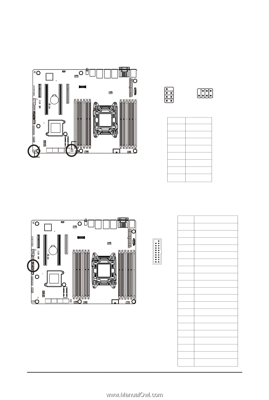
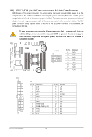
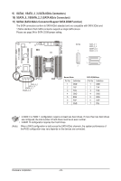
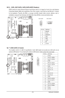
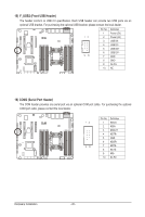
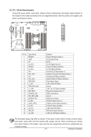
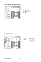
12/13) SATA_SGP1/SATA_SGP2 (SATA SGPIO Headers) SGPIO stands for Serial General Purpose Input/Output which is a 4-signal (or 4-wire) bus used between a Host Bus Adapter (HBA) and a backplane. Out of the 4 signals, 3 are driven by the HBA and 1 is driven by the backplane. Typically, the HBA is a storage controller located inside a server, desktop, rack or workstation computer that interfaces with Hard disk drives (HDDs) to store and retrieve data. SATA_SGP1 12 78 SATA_SGP2 2 8 1 7 SATA_SGP2 SATA_SGP1 Pin No. 1 2 3 4 5 6 7 8 Definition DATAIN No Pin DATAOUT GND GND LOAD NC CLOCK 14) F_USB3 (USB 3.0 Header) The headers conform to USB 3.0 specification. Each USB header can provide two USB ports via an optional USB bracket. For purchasing the optional USB bracket, please contact the local dealer. Pin No. Definition 1 Power 20 1 2 IntA_P1_SSRX- 3 IntA_P1_SSRX+ 4 GND 5 IntA_P1_SSTX- 6 IntA_P1_SSTX+ 11 10 7 GND 8 IntA_P1_D- 9 IntA_P1_D+ 10 NC 11 IntA_P2_D+ 12 IntA_P2_D- 13 GND 14 IntA_P2_SSTX+ 15 IntA_P2_SSTX- 16 GND 17 IntA_P2_SSRX+ 18 IntA_P2_SSRX- 19 Power 20 No Pin - 25 - Hardware Installation
-
 1
1 -
2
-
3
-
4
-
5
-
6
-
7
-
8
-
9
-
10
-
11
-
12
-
13
-
14
-
15
-
16
-
17
-
18
-
19
-
 20
20 -
 21
21 -
 22
22 -
 23
23 -
 24
24 -
 25
25 -
 26
26 -
 27
27 -
 28
28 -
 29
29 -
 30
30 -
31
-
32
-
33
-
34
-
35
-
36
-
37
-
38
-
39
-
40
-
41
-
42
-
43
-
44
-
45
-
46
-
47
-
48
-
49
-
50
-
51
-
52
-
53
-
54
-
55
-
56
-
57
-
58
-
59
-
60
-
61
-
62
-
63
-
64
-
65
-
66
-
67
-
68
-
69
-
70
-
71
-
72
-
73
-
74
-
75
-
76
-
77
-
78
-
79
-
80
-
81
-
82
-
83
-
84
-
85
-
86
-
87
-
88
-
89
-
90
-
91
-
92
-
93
-
94
-
95
-
96
-
97
-
98
-
99
-
100
-
101
-
102
-
103
-
104
-
105
-
106
-
107
-
108
-
109
-
110
-
111
-
112
-
113
-
114
-
115
-
116
-
117
-
118
-
119
-
120
-
121
-
122
-
123
-
124
-
125
 |
 |