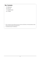
Gigabyte MU70-SU0 Manual - Page 8
Force to Stop FRB Timer jumper
 |
View all Gigabyte MU70-SU0 manuals
Add to My Manuals
Save this manual to your list of manuals |
Page 8 highlights
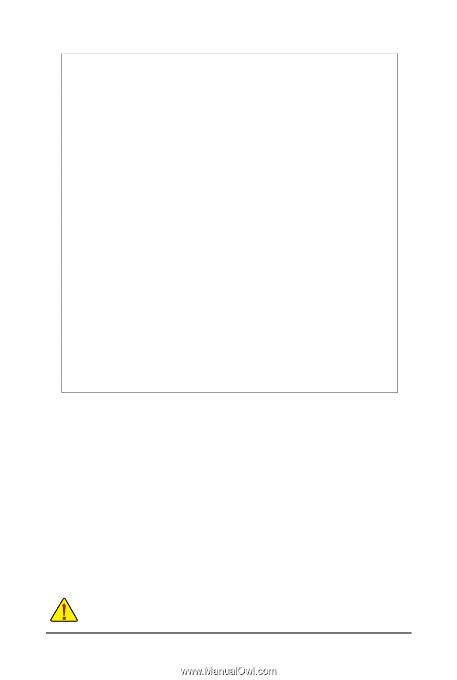
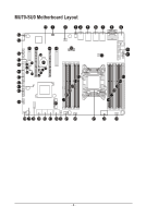
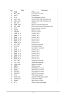
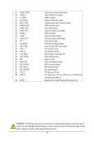
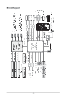
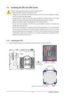
41 CASE_OPEN 42 USB3_A 43 F_USB3 44 SW_RAID1 45 BIOS_PWD 46 PMBUS_SEL 47 HSME_SEL 48 LAN4_ACT1 49 FUSB_2 50 COM2 51 LAN3_ACT1 52 FP_1 53 S3_MASK 54 BMC_FRB 55 PCIE_1 56 PCIE_2 57 LED_BMC1 58 CLR_CMOS 59 BAT 60 BIOS_WP 61 BIOS_RCVR 62 ME_RCVR 63 ME_UPDATE 64 PCIE_3 65 PCIE_4 66 MEZZ_1 Case open intrusion alert header Type A USB 3.0 connector USB3.0 header Software RAID Key jumper Clearing Supervisor Password jumper PMbus select jumper Host select jumper LAN port 4 active LED header USB 2.0 header Serial port cable header LAN port 3 active LED header Front panel header S3 Power On Select jumper Force to Stop FRB Timer jumper PCI Express x4 slot PCI Express x16 slot BMC firmware readiness LED Clear CMOS jumper Battery socket BIOS write protect jumper BIOS recovery jumper ME recovery jumper ME update jumper PCI Express x16 slot PCI Express x16 slot (Running at x8/Shared bandwidth with MEZZ_1) Mezzine slot (x4 slot/Proprietary/Running at x4) CAUTION! If a SATA type hard drive is connected to the motherboard, please ensure the jumper is closed and set to 2-3 pins (Default setting), in order to reduce any risk of hard disk damage. Please refer to Page 34 for SATA_DOM jumper setting instruction. - 8 -
-
 1
1 -
2
-
 3
3 -
 4
4 -
 5
5 -
 6
6 -
 7
7 -
 8
8 -
 9
9 -
 10
10 -
 11
11 -
 12
12 -
 13
13 -
14
-
15
-
16
-
17
-
18
-
19
-
20
-
21
-
22
-
23
-
24
-
25
-
26
-
27
-
28
-
29
-
30
-
31
-
32
-
33
-
34
-
35
-
36
-
37
-
38
-
39
-
40
-
41
-
42
-
43
-
44
-
45
-
46
-
47
-
48
-
49
-
50
-
51
-
52
-
53
-
54
-
55
-
56
-
57
-
58
-
59
-
60
-
61
-
62
-
63
-
64
-
65
-
66
-
67
-
68
-
69
-
70
-
71
-
72
-
73
-
74
-
75
-
76
-
77
-
78
-
79
-
80
-
81
-
82
-
83
-
84
-
85
-
86
-
87
-
88
-
89
-
90
-
91
-
92
-
93
-
94
-
95
-
96
-
97
-
98
-
99
-
100
-
101
-
102
-
103
-
104
-
105
-
106
-
107
-
108
-
109
-
110
-
111
-
112
-
113
-
114
-
115
-
116
-
117
-
118
-
119
-
120
-
121
-
122
-
123
-
124
-
125
 |
 |