Harbor Freight Tools 34706 User Manual - Page 10
Important
 |
View all Harbor Freight Tools 34706 manuals
Add to My Manuals
Save this manual to your list of manuals |
Page 10 highlights
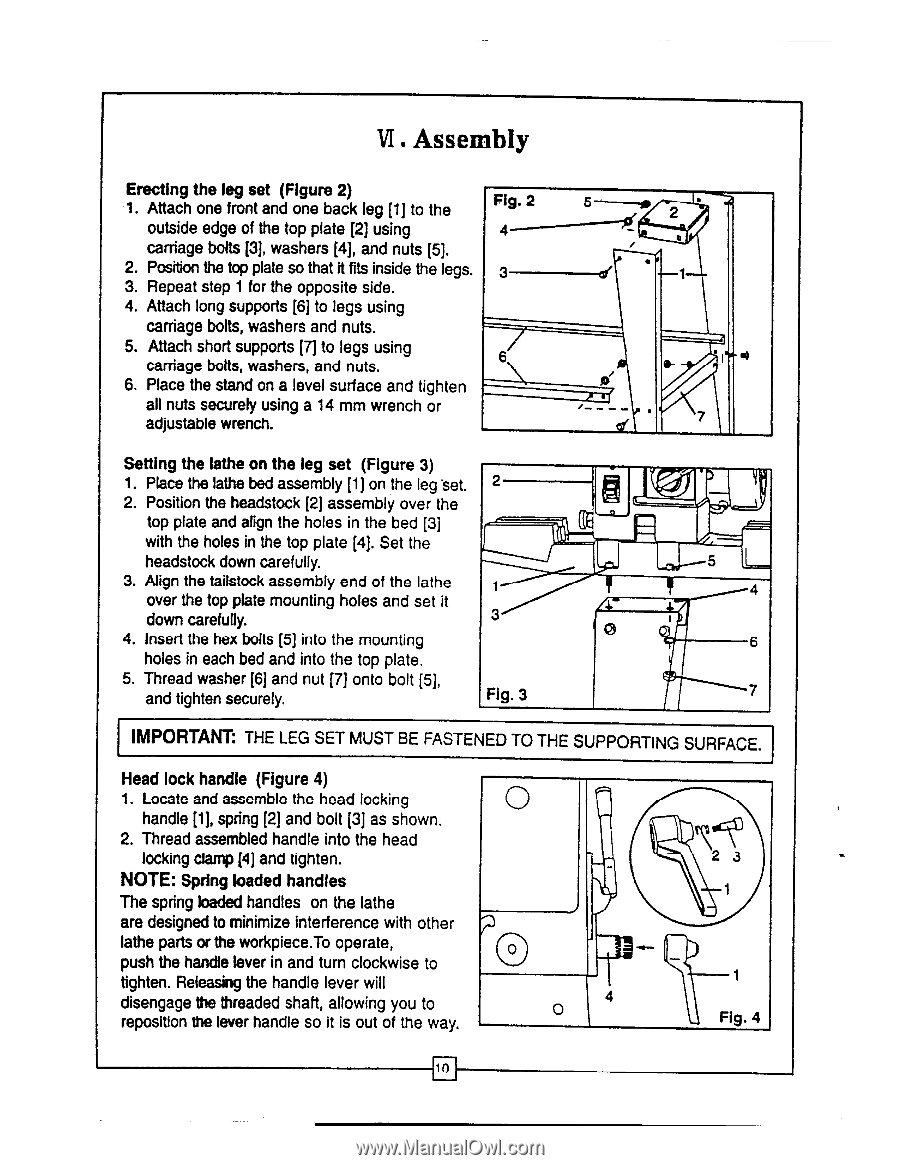
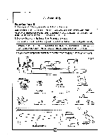
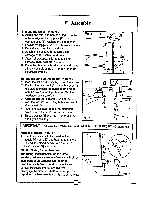
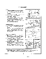
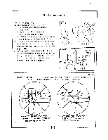
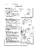
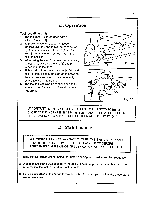
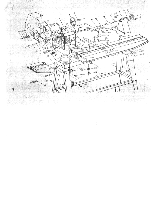
VI.Assembly Erecting the leg set (Figure 2) 1. Attach one front and one back leg [1] to the outside edge of the top plate [2] using carriage bolts [3], washers [4], and nuts [5]. 2. Position the top plate so that it fits inside the legs. 3. Repeat step 1 for the opposite side. 4. Attach long supports [6] to legs using carriage bolts, washers and nuts. 5. Attach short supports [7] to legs using carriage bolts, washers, and nuts. 6. Place the stand on a level surface and tighten all nuts securely using a 14 mm wrench or adjustable wrench. Fig. 2 3 6 2 a( 7 Setting the lathe on the leg set (Figure 3) 1. Place the lathe bed assembly [1] on the leg 'set. 2 2. Position the headstock [2] assembly over the top plate and align the holes in the bed [3] with the holes in the top plate [4]. Set the headstock down carefully. 3. Align the tailstock assembly end of the lathe f over the top plate mounting holes and set it down carefully. 3 4. Insert the hex bolts [5] into the mounting / 47 0 holes in each bed and into the top plate. 5. Thread washer [6] and nut [7] onto bolt [5], and tighten securely. Fig. 3 5 1 - 4 6 7 IMPORTANT: THE LEG SET MUST BE FASTENED TO THE SUPPORTING SURFACE. Head lock handle (Figure 4) 1. Locate and assemble the head locking handle [1], spring [2] and bolt [3] as shown. 2. Thread assembled handle into the head locking clamp [4] and tighten. NOTE: Spring loaded handles The spring loaded handles on the lathe are designed to minimize interference with other lathe parts or the workpiece.To operate, push the handle lever in and turn clockwise to tighten. Releasing the handle lever will disengage the threaded shaft, allowing you to reposition the lever handle so it is out of the way. 4 0 2 3 1 1 Fig. 4
-
 1
1 -
2
-
3
-
4
-
 5
5 -
 6
6 -
 7
7 -
 8
8 -
 9
9 -
 10
10 -
 11
11 -
 12
12 -
 13
13 -
 14
14 -
 15
15 -
16
-
17
-
18
 |
 |