Harbor Freight Tools 34706 User Manual - Page 11
to the bed
 |
View all Harbor Freight Tools 34706 manuals
Add to My Manuals
Save this manual to your list of manuals |
Page 11 highlights
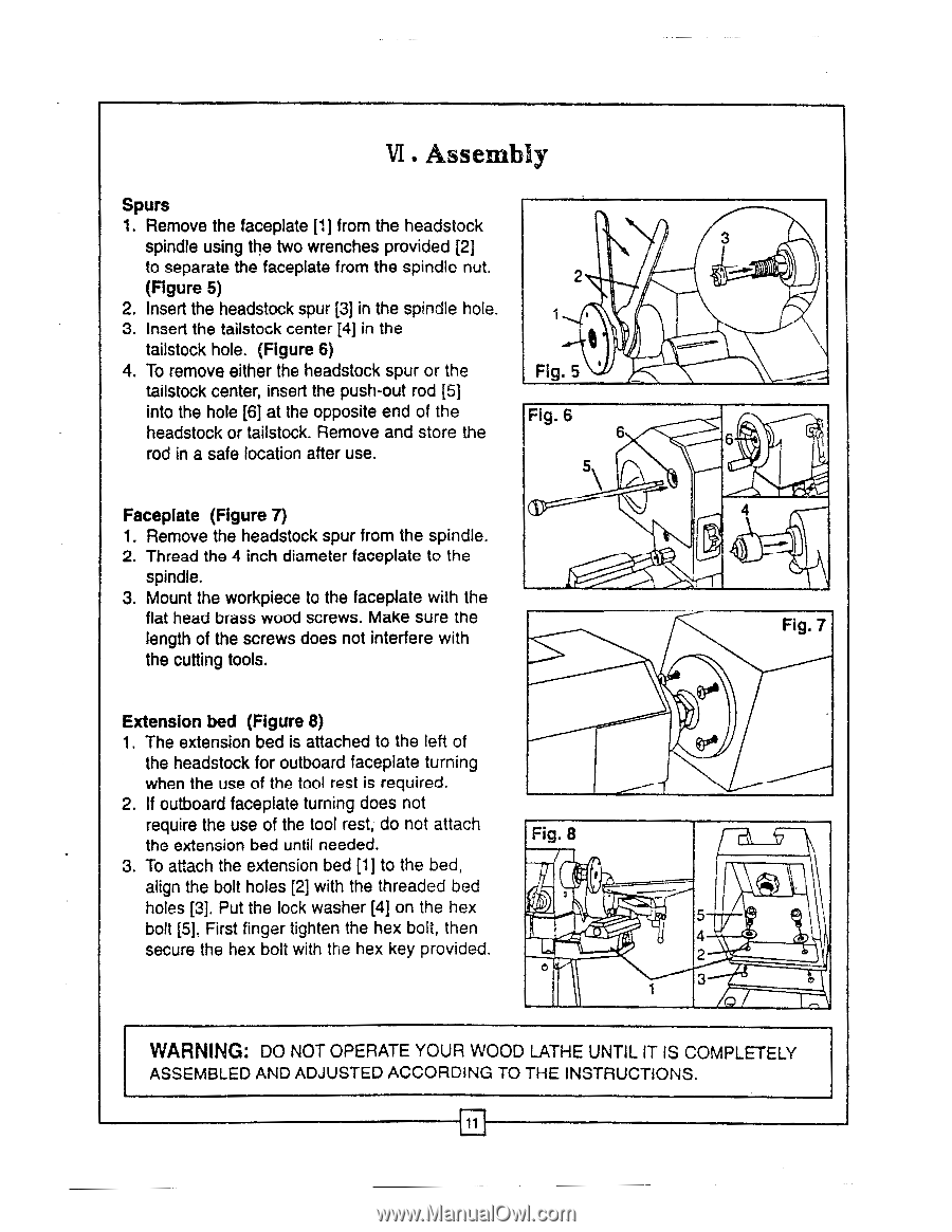
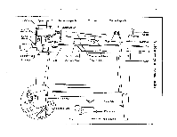
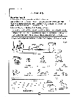
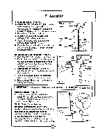
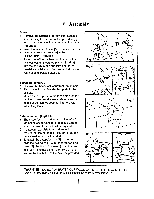
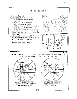
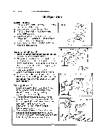
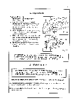
VI . Assembly Spurs 1. Remove the faceplate [1] from the headstock spindle using the two wrenches provided [2] to separate the faceplate from the spindle nut. (Figure 5) 2. Insert the headstock spur [3] in the spindle hole. 3. Insert the tailstock center [4] in the tailstock hole. (Figure 6) 4. To remove either the headstock spur or the tailstock center, insert the push-out rod [5] into the hole [6] at the opposite end of the headstock or tailstock. Remove and store the rod in a safe location after use. Faceplate (Figure 7) 1. Remove the headstock spur from the spindle. 2. Thread the 4 inch diameter faceplate to the spindle. 3. Mount the workpiece to the faceplate with the flat head brass wood screws. Make sure the length of the screws does not interfere with the cutting tools. 2 Fig. 5 Fig. 6 6 5 \ Extension bed (Figure 8) 1. The extension bed is attached to the left of the headstock for outboard faceplate turning when the use of the tool rest is required. 2. If outboard faceplate turning does not require the use of the tool rest, do not attach the extension bed until needed. 3. To attach the extension bed [1] to the bed, align the bolt holes [2] with the threaded bed holes [3]. Put the lock washer [4] on the hex bolt [5]. First finger tighten the hex bolt, then secure the hex bolt with the hex key provided. Fig. 8 I 3 6 4 Fig. 7 5 4 2 3 WARNING: DO NOT OPERATE YOUR WOOD LATHE UNTIL IT IS COMPLETELY ASSEMBLED AND ADJUSTED ACCORDING TO THE INSTRUCTIONS. 11
-
 1
1 -
2
-
3
-
4
-
5
-
 6
6 -
 7
7 -
 8
8 -
 9
9 -
 10
10 -
 11
11 -
 12
12 -
 13
13 -
 14
14 -
 15
15 -
 16
16 -
17
-
18
 |
 |