Harbor Freight Tools 38144 User Manual - Page 6
Mounting, Assembly
 |
View all Harbor Freight Tools 38144 manuals
Add to My Manuals
Save this manual to your list of manuals |
Page 6 highlights
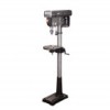
SAFETy SETUp Specifications Motor power Electrical Rating Drill chuck capacity Spindle Stroke Swing column Diameter Dry Table Table Slot Overall Height Weight product Use 3/4 HP - 16 speeds ranging from 220 to 3600 RPM 120VAC, 60Hz, 7.5A, Single-Phase 7/64″ to 5/8″ 3-1/8″ 13″ 2- 57/64″ 11-7/8″ Diameter 1/2″ 62-3/4″ 125 lbs14a For heavy-duty use on metal, plastic or wood materials. Table rotates 360º and tilts 0-45º in 1º increments. Setup - Before Use: Read the ENTIRE IMpORTANT SAFETy INFORMATION section at the beginning of this manual including all text under subheadings therein before set up or use of this product. TO pREVENT SERIOUS INJURy FROM AccIDENTAL OpERATION: Turn the power Switch of the tool off and unplug the tool from its electrical outlet before performing any procedure in this section. Note: For additional information regarding the parts listed in the following pages, refer to the Assembly Diagram near the end of this manual. Mounting Secure the tool to a supporting structure before use. Before assembly, bolt the Base to a flat, level, solid floor location capable of supporting the weight of the drill press and any workpieces. Verify that installation surface has no hidden utility lines before drilling or driving screws. Assembly column Assembly to Base 1. With the Base (6B) on a flat level surface, bolt on the Column Support (4B) using the four M10x40mm Hex Head screws (5B). 2. Tighten firmly. 3. Insert the Column (1B) into the Support and firmly secure with the Hex Socket Set Screws (3B). Note: It may be necessary to loosen the Set Screws beforehand, as they may protrude into the tube preventing the Column from sliding in fully. OpERATION MAINTENANcE Page 6 For technical questions, please call 1-888-866-5797. Item 38144
-
 1
1 -
 2
2 -
 3
3 -
 4
4 -
 5
5 -
 6
6 -
 7
7 -
 8
8 -
 9
9 -
 10
10 -
 11
11 -
 12
12 -
13
-
14
-
15
-
16
 |
 |
