Harbor Freight Tools 61454 User Manual - Page 7
Assembly
 |
View all Harbor Freight Tools 61454 manuals
Add to My Manuals
Save this manual to your list of manuals |
Page 7 highlights
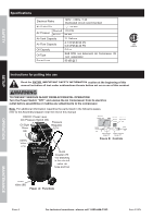
SAFETY SETUP Assembly Tank (70) Cylinder Head (7) Nut (24) Hex Nut (65) Foot Pad (67) Figure C Wheel (63) Washer (68) Sleeve (64a) Screw (69) Washer (64b) Bolt (64) 1. Attach the Wheels (63) to the Tank (70), using the Bolts (64), Washers (64b), Sleeves (64a), and Hex Nuts (65). Attach the Foot Pads (67) to the bottom of the Tank (70) using the Screws (69) and Washers (68). Handle (72) Air Filter (6) Figure E 3. Thread the Air Filter (6) onto the side of the Cylinder Head (7). 4. Break in the new Air Compressor as follows: a. Turn the Power Switch off and unplug the unit. Insert a male coupler (sold separately) into the female Quick Coupler and fully open all regulators and valves. b. Plug in the Power Cord. c. Turn the Power Switch ON. d. Let the unit run for 30 minutes. Air will expel freely through the Coupler. e. Turn the Power Switch OFF. f. Unplug the Power Cord and remove the male coupler. Figure D Tank (70) Bolts (71) 2. Slide the Handle (72) into the two slots on the top of the Tank (70) and secure in place with four Bolts (71). 5. Connect a regulator valve, an inline shut off valve and a 1/4″ NPT air hose to the Quick Coupler (all sold separately). The air hose must be long enough to reach the work area with enough extra length to allow free movement while working. Note: An in-line shutoff ball valve is an important safety device because it controls the air supply even if the air hose is ruptured. The shutoff valve should be a ball valve because it can be closed quickly. 6. Depending on the tool which you will be using with this compressor, you may need to incorporate additional components, such as an in-line oiler, a filter, or a dryer (all sold separately), as shown on Figure F on page 8 and Figure G on page 9. Consult your air tool's manual for needed accessories. OPERATION MAINTENANCE Item 61454 For technical questions, please call 1-800-444-3353. Page 7
-
 1
1 -
 2
2 -
 3
3 -
 4
4 -
 5
5 -
 6
6 -
 7
7 -
 8
8 -
 9
9 -
 10
10 -
 11
11 -
 12
12 -
13
-
14
-
15
-
16
-
17
-
18
-
19
-
20
 |
 |
