Harman Kardon AVR 1565 Owners Manual - Page 15
Harman Kardon AVR 1565 Manual
 |
View all Harman Kardon AVR 1565 manuals
Add to My Manuals
Save this manual to your list of manuals |
Page 15 highlights
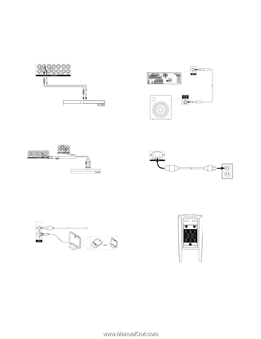
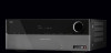
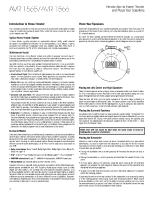
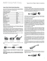
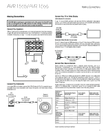
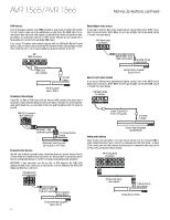
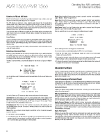
AVR 1565/AVR 1566 Audio recorders Connect an analog audio recorder's inputs to the AVR's analog audio Tape Out connectors. You can record any analog audio input signal. AVR Analog Audio Recorder Connectors Making Connections, continued, and Set Up the Remote Control Connect the 12V Trigger Output If your system has equipment that can be controlled by a DC trigger signal, connect it to the AVR's 12V Trigger connector with a mono 1/8-inch (3.5mm) mini-plug interconnect cable. The AVR will supply a 12V DC (100mA) trigger signal at this connection whenever it is powered on. AVR Mono 1/8-inch (3.5mm) Mini-Plug Interconnect (not supplied) Stereo Audio Cable (not supplied) To Stereo Analog Record Outputs Device with Trigger in Connector Analog Recording Device Video recorders Connect an analog video recorder's video input connector to the AVR's Video 2 Out Composite Video connector, and its audio input connectors to the AVR's Video 2 Out Analog Audio connectors. You can record any composite video signal. AVR Analog Video Connectors Connect to AC Power Connect the AC power cord to the AVR's AC Input connector and then to a working AC power outlet. AVR AC Input Connector AC Power Outlet Power Cord (supplied) AVR Analog Audio Connectors Analog Audio/Video Cable (not supplied) To Analog Audio/Video Record Inputs Analog Video Recording Device Connect the Radio Antennas • Connect the supplied FM antenna to the AVR's FM 751 Radio Antenna connector. For the best reception, extend the FM antenna as far as possible. • Bend and fold the base of the supplied AM antenna as shown and connect the antenna wires to the AVR's AM and Gnd connectors. (You can connect either wire to either connector.) Rotate the antenna as necessary to minimize background noise. AVR Radio Antenna Connectors FM Antenna (supplied) Set Up the Remote Control Install the Batteries in the Remote Control Remove the remote control's battery cover, insert the three supplied AAA batteries as shown in the illustration, and replace the battery cover. AM Antenna (supplied) Bend and fold base NOTE: Remove the protective plastic from the AVR's front panel to keep it from reducing the remote control's effectiveness. 15
-
 1
1 -
2
-
3
-
4
-
5
-
6
-
7
-
8
-
9
-
 10
10 -
 11
11 -
 12
12 -
 13
13 -
 14
14 -
 15
15 -
 16
16 -
 17
17 -
 18
18 -
 19
19 -
 20
20 -
21
-
22
-
23
-
24
-
25
-
26
-
27
-
28
-
29
-
30
-
31
-
32
-
33
-
34
-
35
-
36
-
37
-
38
-
39
-
40
-
41
 |
 |