Harman Kardon AVR 3600 Owners Manual - Page 24
Installation - manual
 |
View all Harman Kardon AVR 3600 manuals
Add to My Manuals
Save this manual to your list of manuals |
Page 24 highlights
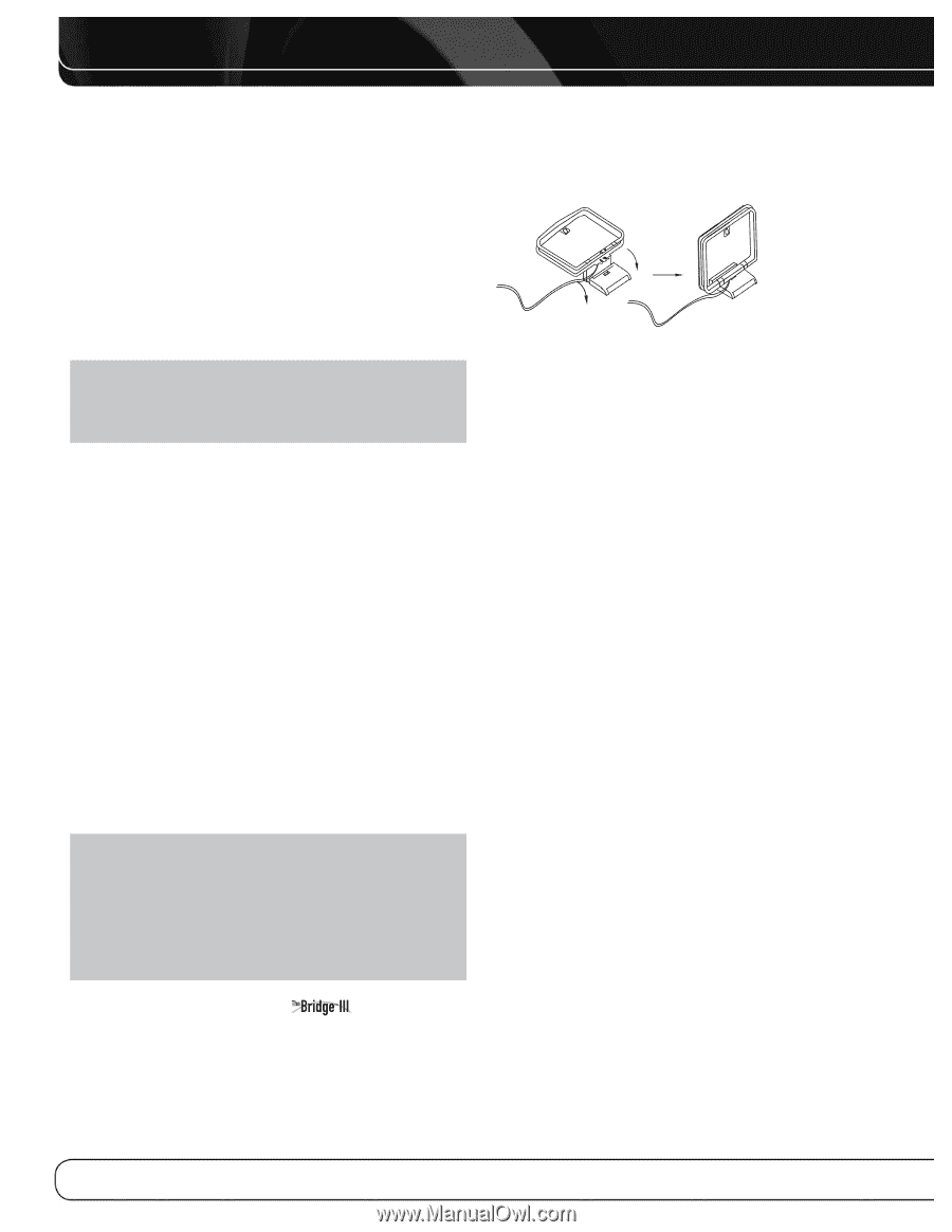
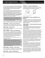
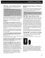
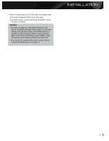
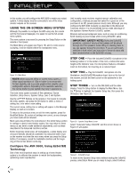
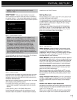
INSTALLATION You are now ready to begin installing the AVR. Before beginning to connect the various components to the receiver, turn off all devices, including the AVR 3600, and unplug their power cords. Don't plug in any of the power cords until you have finished making all of your connections. The receiver generates heat. Select a location that leaves several inches of space on all sides. Avoid completely enclosing the receiver inside an unventilated cabinet. Place components on separate shelves rather than stacking them directly on top of the receiver. Never block the AVR's ventilation slots on the top and side panels. Doing so could cause the AVR to overheat, with potentially serious consequences. Some shelf surface finishes are delicate. Try to select a location with a sturdy surface finish. TIP: Label each cable before connecting it, to avoid mistakes. Write a description of the cable on a blank adhesive label, e.g., "DVD", and fold the label around the cable about 6 inches from the end to be plugged into the AVR. Almost all of the following installation steps are optional, depending on your system. Skip any step that does not apply to your system. STEP ONE - Connect Source Devices Leaving all AC power cords unplugged, connect the source devices to the AVR using the audio and video inputs you assigned in Table 2. STEP TWO - Connect TV Connect the system-best video input on the TV to the corresponding video monitor output on the AVR. STEP THREE - Connect Loudspeakers After you have placed your loudspeakers in the room as explained on page 21, connect each speaker to its color-coded terminal on the AVR. Maintain proper polarity by connecting the negative terminal on the speaker (usually colored black) to the negative terminal on the AVR (also colored black); and the positive terminal on the speaker (usually red) to the positive terminal on the AVR (color varies by channel; see Table 1 on page 18). If you have a subwoofer, connect its line-level or LFE input to the purple Subwoofer Output. NOTE: If the subwoofer only has speaker-level inputs, after you have configured the AVR using EzSet/EQ technology as described on page 28, connect the subwoofer's left and right speaker input terminals to the AVR's Front Left and Front Right Speaker Outputs, then connect the front left and right main speakers to the subwoofer's left and right speaker output terminals. Consult the owner's manual for the subwoofer for specific installation instructions. STEP FOUR - Connect Dock To enjoy content stored on a compatible iPod or iPhone (not included), connect The Bridge III dock (included) to its proprietary connector. STEP FIVE - Connect FM Antenna Connect the included FM antenna to the 75-ohm FM antenna terminal. STEP SIX - Connect AM Antenna Assemble the included AM antenna (see Figure 16) and connect it to the AM and Ground antenna terminals. The antenna is not polarized, and either lead may be connected to either terminal. Figure 16 - AM Antenna Assembly STEP SEVEN - Connect SIRIUS Tuner Module If you have purchased an optional SIRIUS tuner module designed for SIRIUS Ready® devices, plug it into the SIRIUS jack. Purchase a subscription and activate the module, following the instructions posted at www.sirius.com. Place the module within view of a south-facing window. STEP EIGHT - Connect Remote IR Inputs and Outputs The AVR 3600 is equipped with a Remote IR Input, a Zone 2 Input, an A-BUS IR Output and both full-carrier and stripped Remote IR Outputs to facilitate use of your system with a remote control in a variety of situations. When the AVR 3600 is placed inside a cabinet or facing away from the listener, connect an external IR receiver, such as the optional Harman Kardon HE 1000, to the Remote IR Input jack. For multizone operation, connect an optional IR receiver, keypad or other control device to the Zone 2 IR Input for remote control of the AVR 3600 (and any sources connected to the AVR's Remote IR Output) from the remote zone. Signals transmitted through the Zone 2 IR Input will control source selection and volume for the main or remote zone, depending on the setting of the remote's Zone Selector. If a source device is shared with the main listening area, any control commands issued to that source will also affect the main room. If any source devices are equipped with a compatible Remote IR Input, use a 1/8 inch mini-plug interconnect cable (not included) to connect the AVR's Remote IR Output to the source device's Remote IR Input. The AVR 3600 outputs a "stripped carrier" IR signal through the Remote IR Output, but a full-carrier IR signal is available at the Carrier Remote IR Output. The AVR 3600 is also equipped with an A-BUS IR Output for dedicated use with the A-BUS multizone system. Any devices connected to this output will only respond to commands transmitted through the A-BUS system. To control more than one source device through the Remote IR Output, connect all sources in "daisy chain" fashion, connecting each device's IR output to the next device's IR input, starting with the AVR. Connect devices expecting a full-carrier IR signal to the Carrier Remote IR Output. Use the Remote IR Output for devices expecting a stripped signal. 24
-
 1
1 -
2
-
3
-
4
-
5
-
6
-
7
-
8
-
9
-
10
-
11
-
12
-
13
-
14
-
15
-
16
-
17
-
18
-
 19
19 -
 20
20 -
 21
21 -
 22
22 -
 23
23 -
 24
24 -
 25
25 -
 26
26 -
 27
27 -
 28
28 -
 29
29 -
30
-
31
-
32
-
33
-
34
-
35
-
36
-
37
-
38
-
39
-
40
-
41
-
42
-
43
-
44
-
45
-
46
-
47
-
48
-
49
-
50
-
51
-
52
-
53
-
54
-
55
-
56
-
57
-
58
-
59
-
60
-
61
-
62
-
63
-
64
-
65
-
66
 |
 |