Harman Kardon AVR 510 Owners Manual - Page 16
System and Power Connections - stereo receiver
 |
View all Harman Kardon AVR 510 manuals
Add to My Manuals
Save this manual to your list of manuals |
Page 16 highlights
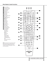
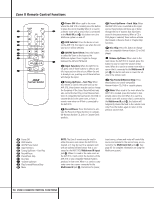
Installation and Connections Video Equipment Connections Video equipment is connected in the same manner as audio components. Again, the use of highquality interconnect cables is recommended to preserve signal quality. 1. Connect a VCR's or other video source's audio and video Play/Out jacks to the Video 1 or Video 2 In jacks £ik 35 on the rear panel. The Audio and Video Record/In jacks on the VCR should be connected to the Video 1 or Video 2 Out jacks ∞gj 36 on the AVR 510. 2. Connect the analog audio and video outputs of a satellite receiver, cable TV converter or television set or any other video source to the Video 3 h 34 jacks. 3. Connect the analog audio and video outputs of a DVD or laser disc player to the DVD jacks §f. 4. Connect the digital audio outputs of a DVD player, satellite receiver, cable box or HDTV converter to the appropriate Optical or Coaxial Digital Inputs 31 32 #%. 5. Connect the Video Monitor Output › jacks on the receiver to the composite or S-Video input of your television monitor or video projector. 6. If your DVD player and monitor both have component video connections, connect the component outputs of the DVD player to the DVD Component Video Inputs b. Note that even when component video connections are used, the audio connections should still be made to either the analog DVD Audio Inputs § or any of the Optical or Coaxial Digital Input jacks 31 32 . 7. If another component video device is available, connect it to the Video 2 Component Video Input jacks a. The audio connections for this device should be made to either the Video 2 Audio Input jacks 35 or any of the Optical or Coaxial Digital Input jacks 31 32 . 8. If the component video inputs are used, connect the Component Video Output · to the component video inputs of your TV, projector or display device. Video Connection Notes: • When the component video jacks are used, the on-screen menus will not be visible. You must switch to the standard composite or S-Video input on your TV to view those menus. • The AVR 510's component video system is designed for standard video rate (NTSC/480i) video from DVD players and similar devices. While it will operate with high-definition signals, or progressive-scan DVD players, the quality may be slightly less than with a direct connection. • The AVR 510 will accept either standard composite, S-Video or Y/Pr/Pb component video signals. However, it will not convert composite or S signals to component video. • Component, S- or composite video signals may only be viewed in their native formats. Component or S-Video inputs may only be viewed when the AVR 510 is connected to a TV or video display that is capable of receiving that type of signal. System and Power Connections The AVR 510 is designed for flexible use with multiroom systems, external control components and power amplifiers. Main Room Remote Control Extension If the receiver is placed behind a solid or smoked glass cabinet door, the obstruction may prevent the remote sensor from receiving commands. In this event, an optional remote sensor may be used. Connect the output of the remote sensor to the Remote IR Input jack d. If other components are also prevented from receiving remote commands, only one sensor is needed. Simply use this unit's sensor or a remote eye by running a connection from the Remote IR Output jack c to the Remote IR Input jack on Harman Kardon or other compatible equipment. Multiroom IR Link The remote room IR receiver should be connected to the AVR 510 via standard coaxial cable. Plug the IR connection cable into the Multiroom IR Input jack e on the AVR 510's rear panel. If other Harman Kardon compatible source equipment is part of the main room installation, the Remote IR Output jack c on the rear panel should be connected to the IR IN jack on source equipment. This will enable the remote room location to control source equipment functions. NOTE: All remotely controlled components must be linked together in a "daisy chain". Connect the IR OUT jack of one unit to the IR IN of the next to establish this chain. Multiroom Audio Connections Depending on the distance from the AVR 510 to the remote room, two options are available for audio connection: Option 1: Use high-quality, shielded audio interconnect cable from the AVR 510's location to the remote room. In the remote room, connect the interconnect cable to a stereo power amplifier. The amplifier will be connected to the room's speakers. No volume control is required, as the AVR 510 and the remote IR link will provide that function. At the AVR 510, plug the audio interconnect cables into the Multiroom Output jacks , on the AVR 510's rear panel. NOTE: The remote power amplifier must have signal-sensing capability or be left on constantly to ensure automatic operation in the remote room. Option 2: Place the amplifier that will provide power to the remote location speakers in the same room as the AVR 510, and connect the Multiroom Output jacks , on the rear panel of the AVR 510 to the audio input of the remote room amplifier. Use the appropriate speaker wire to connect the optional power amplifier to the remote speakers. High-quality wire of at least AWG14 is recommended for long multiroom connections. 16 INSTALLATION AND CONNECTIONS
-
 1
1 -
2
-
3
-
4
-
5
-
6
-
7
-
8
-
9
-
10
-
 11
11 -
 12
12 -
 13
13 -
 14
14 -
 15
15 -
 16
16 -
 17
17 -
 18
18 -
 19
19 -
 20
20 -
 21
21 -
22
-
23
-
24
-
25
-
26
-
27
-
28
-
29
-
30
-
31
-
32
-
33
-
34
-
35
-
36
-
37
-
38
-
39
-
40
-
41
-
42
-
43
-
44
-
45
-
46
-
47
-
48
-
49
-
50
-
51
-
52
-
53
-
54
-
55
-
56
 |
 |
