Harman Kardon AVR 510 Owners Manual - Page 2
Audio/ Video Receiver - remote control
 |
View all Harman Kardon AVR 510 manuals
Add to My Manuals
Save this manual to your list of manuals |
Page 2 highlights
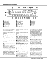
AVR 510 Audio/Video Receiver 3 Introduction 4 Safety Information 4 Unpacking 5 Front Panel Controls 7 Front Panel Information Display 9 Rear Panel Connections 11 Main Remote Control Functions 14 Zone II Remote Control Functions 15 Installation and Connections 18 System Configuration 20 Input Setup 20 Surround Setup 21 Delay Settings 22 Speaker Setup 23 Output Level Adjustment 23 Crossover Frequency 24 Manual Output Level Adjustment 26 Operation 26 Basic Operation 26 Source Selection 27 Surround Mode Chart 28 Surround Mode Selection 28 Digital Audio Playback 28 Selecting a Digital Source 30 Tuner Operation 31 Tape Recording 31 Front Panel Input/Output Connections 31 Output Level Trim Adjustment 32 6-Channel Direct Input 33 Advanced Features 33 Display Brightness 33 Turn-On Volume Level 33 Semi-OSD Settings 35 Multiroom Operation 36 Programming the Remote 36 Direct Code Entry 36 Auto Search Method 36 Code Readout 37 Learning Codes 37 Erasing Learned Codes 37 Macro Programming 38 Programmed Device Functions 39 Volume Punch-Through 39 Channel Control Punch-Through 40 Reassigning Device Control Selectors 41 Function List 43 Setup Code Tables 53 Troubleshooting Guide 53 Processor Reset 54 Notes 55 Technical Specifications Typographical Conventions In order to help you use this manual with the remote control, front panel controls and rear panel connections, certain conventions have been used. EXAMPLE - (bold type) indicates a specific remote control or front panel button, or rear panel connection jack EXAMPLE - (OCR type) indicates a message that is visible on the front panel information display EXAMPLE - (outlined type) indicates a lit indicator in the front panel information display 1 - (number in a square) indicates a specific front panel control ¡ - (number in a circle) indicates a rear panel connection a - (number in an oval) indicates a button or indicator on the remote A - (letter in a square) indicates an indicator in the front panel display å - (letter in an oval) indicates a button on the Zone II remote 2 TABLE OF CONTENTS
-
 1
1 -
 2
2 -
 3
3 -
 4
4 -
 5
5 -
 6
6 -
 7
7 -
 8
8 -
9
-
10
-
11
-
12
-
13
-
14
-
15
-
16
-
17
-
18
-
19
-
20
-
21
-
22
-
23
-
24
-
25
-
26
-
27
-
28
-
29
-
30
-
31
-
32
-
33
-
34
-
35
-
36
-
37
-
38
-
39
-
40
-
41
-
42
-
43
-
44
-
45
-
46
-
47
-
48
-
49
-
50
-
51
-
52
-
53
-
54
-
55
-
56
 |
 |
