Harman Kardon HK330VI Owners Manual - Page 7
components
 |
View all Harman Kardon HK330VI manuals
Add to My Manuals
Save this manual to your list of manuals |
Page 7 highlights
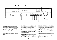
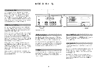
TAPE 1 and TAPE 2 inputs and outputs (tape monitor loops) correspond to their opposite sockets on your tape deck(s). That is, out on the cassette deck connects to in on the receiver. When employing signal processing devices such as an equalizer, expander, dynamic noise suppressor, or special speaker equalization box, connect them through one or the other of the receiver's tape monitor loops. If you have such components and one cassette deck, connect all outboard signal processing devices to the TAPE 1 inputs and outputs on the hk330 Vi. Your tape deck is then connected to the tape monitor loop of the last outboard signal processing device (see Fig. 4 on next page). Switching the receiver's TAPE MONITOR source/monitor switch to "monitor" and 1/2 switch to "1" now switches in your signal processor(s). To use the cassette deck, press the Tape Monitor buttons on the outboard components. The VIDEO input may be used for any line level source including VCR's, audio output from a TV, etc. Turntable 0@@O0 0 CD Player VCR Figure 3, Connection Diagram 7 %ow Tape 2 Tape 1 Speaker 1 - R Speaker 1 - L A A -O- O Speaker 2 -R Speaker 2 -L
-
 1
1 -
 2
2 -
 3
3 -
 4
4 -
 5
5 -
 6
6 -
 7
7 -
 8
8 -
 9
9 -
 10
10 -
 11
11 -
 12
12
 |
 |
