Harman Kardon HK330VI Owners Manual - Page 8
Monitor,
 |
View all Harman Kardon HK330VI manuals
Add to My Manuals
Save this manual to your list of manuals |
Page 8 highlights
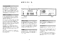
hk330 Vi In Out Equalizer or other Sound Processor MAIN In Out -4 •- MONITOR In Out -• • • Cassette Deck In Out Figure 4 Depending on the type of antenna connector, attach your FM antenna to either the terminals marked 300O BAL or 75O UNBAL at the left side of the chassis back. The flexible dipole FM antenna supplied with your receiver should be sufficient for reception of most stations. If you are adding an external AM antenna, connect a ground wire to the terminal marked GND next to the 300O BAL. NOTE: Roof top FM antenna mast should be grounded directly to the earth ground using 10-gauge or heavier wire, stand-off insulators and a metal stake. The FM antenna should then be connected to the ground mast via an antenna discharge unit. The quality of your FM and AM reception is directly proportional to the quality of the antenna you use. If you live in a "problem" area or are simply interested in better reception, please refer to APPENDIX I in this manual. Cabling. For optimal sonic performance, you should use the highest quality speaker cables you can afford. However, common "zip cord" from a hardware store can be employed if care is taken to use the proper gauge. This will depend on the distance from your receiver to your speakers. Use the following chart as a guide: WIRE LENGTH Up to 8 ft. Up to 12 ft. Up to 20 ft. Almost any distance GAUGE OF COPPER WIRE 18 gauge 16 gauge 14 gauge Special speaker cable Make sure that both right and left speaker wires are the same length, even if the distance from amp to each speaker is different. Also, avoid coiling any excess wire near or with line level hook-up cords, especially the sensitive cable from your turntable to the receiver. Connection. First, determine the polarity of your speaker wires. If you are using zip cord, they may 1) be different colors, such as silver and copper-colored, 2) have a series of ridges on one conductor, or 3) include a strand of yarn with one conductor. Note that the terminals for both SPEAKER SYSTEM 1 and SPEAKER SYSTEM 2 are marked LEFT and RIGHT with GND (ground) terminals in between. A good practice is to use the red/copper/ridged/yarn conductor for the LEFT/RIGHT (positive) conductors on both receiver and speaker terminals. Use the black/silver/non-ridged/no-yarn conductor for the GND (negative) connection. 1. Strip 1/2 inch of conductor off each speaker conductor. 2. Twist the individual strands together so that no loose strands stick out. 8 3. Taking care to maintain proper polarity (positive to positive/negative to negative), insert 1/2" of conductor into the hole in each speaker terminal connector. Remember, even one loose strand touching another connector can cause a short circuit. 4. If you're using two sets of speakers, repeat these connections for the second pair of loudspeakers, using SPEAKER SYSTEM 2 terminals. 5. Recheck the polarity of both sets of speaker wires, making sure that you have connected "red to red" and "black to black". The hk330 Vi allows up to two sets of speakers to be connected. It is important that the correct impedance speakers are selected to avoid possible damage to the amplifier and/or the speakers. When using only one set of speakers, their impedance must be 8 ohms or greater. When using two sets of speakers, their impedance must be 16 ohms or greater. If you don't know the impedance rating of your speakers, it may be: A) printed on the back of the speaker, B) noted on the speaker's owner's manual, C) available by calling your dealer or the speaker manufacturer. Finally, plug in the hk330 Vi's own power cord after reading the warnings at the beginning of this manual. We recommend that your receiver be plugged directly into a polarized wall socket. If you must use an extension cord or power strip, check that it is terminated in a polarized plug and rated in excess of the power to be drawn as printed on the back panel of your hk330 Vi.
-
 1
1 -
2
-
 3
3 -
 4
4 -
 5
5 -
 6
6 -
 7
7 -
 8
8 -
 9
9 -
 10
10 -
 11
11 -
 12
12
 |
 |
