Harman Kardon HK490I Owners Manual - Page 6
Antennas
 |
View all Harman Kardon HK490I manuals
Add to My Manuals
Save this manual to your list of manuals |
Page 6 highlights
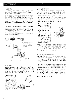
ANTENNAS FM Antenna If experiencing bad FM reception while using the accessory antenna, an outdoor antenna exclusively for FM reception is likely to improve FM reception. The connecting wire between the antenna and the antenna input terminal is called a feeder. Most feeders are 3002 parallel or 75E2 coaxial cables. We recommend type 3C-2V or 5C-2V 752 coaxial cable to be used for this unit to allow it to perform to its fullest capacity. The coaxial cable has a stronger resistance against losses and interference compared with the parallel feeder. If there is a lot of noise while receiving an FM broadcast, we recommend that you make a ground connection. Connect one end of a thick wire to the antenna GND terminal and wind the other end around an earth bar or earth plate and drive it into the ground. CAUTION: Never make a connection to a gas pipe because it may cause fire hazard. FM outdoor antenna 752 coaxial cadle 3002 parallel feeder Accessory antenna Unfold the accessory antenna to a T-shape and fix both ends, facing in the direction that provides optimum reception. Connecting Speakers Connect the speaker wires carefully to the speaker terminals on the rear panel so as not to mistake the left and the right channels and reverse the speaker polarities (+ and -). Use sufficiently thick wire (18 gauge for short lengths, 16-12 gauge for longer lengths). It is recommended to use color-coded wire for easy discrimination of polarities. Speaker wires should be as short as possible, and the left and the right channel wires should have the same length. 1. Remove about 3/4 inch (20 mm) of insulation from the end of each wire and twist the strands of each conductor. 2. After making sure of cor- rect channel and polarity, loosen the speaker termi- \.• nal knob and insert the conductor straight into the recess at the upper-right of the terminal. Tighten the terminal knob, and the end of speaker wire is winded automatically. CAUTION: Two speaker systems can be connected to this unit. The minimum speaker impedance should be 4S2 when only one speaker system is connected. When two speaker systems are connected, care should be taken that net impedance does not become less than 42. Earth bar AM Antenna AM loop antenna attached to this unit allows sufficient reception except in an area where signals are weak. In a fringe area or inside a concrete building where the reception is weak and the sound is unpleasant to the ear, an AM outdoor antenna is likely to improve reception. Place the AM loop antenna as far away from this unit as possible without touching a metal object. The AM loop antenna is fitted to this unit by an antenna holder on the rear panel. To remove the AM loop antenna from the unit, simply pull it out of the holder. AM loop antenna D AM outdoor antenna Connecting Other Components Make certain that the power cord is unplugged from the AC outlet when other components are to be connected to this unit. Unplug or turn off the other components which are already connected to the unit when another piece is to be connected. Connect the plugs correctly to the left channel and right channel jacks. Push the plugs in all the way. Poor seating of the plugs tends to cause noise or intermittent sound. CAUTION: The capacity of the AC convenience outlets at the rear panel are 180W for both SWITCHED and UNSWITCHED. It is very dangerous to connect a component with a capacity for more power. Read the manual or labels on the component to check its power (watt) consumption before connecting it to this unit. 5
-
 1
1 -
 2
2 -
 3
3 -
 4
4 -
 5
5 -
 6
6 -
 7
7 -
 8
8 -
 9
9 -
 10
10 -
 11
11
 |
 |
