Harman Kardon TDC33 Owners Manual - Page 3
System, Right, These, Receptacles, Speakers, Employing, Connectors, Anual, Before, Removing
 |
View all Harman Kardon TDC33 manuals
Add to My Manuals
Save this manual to your list of manuals |
Page 3 highlights
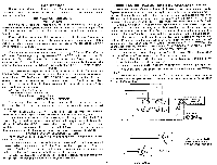
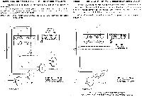
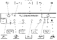
TAPE RECORDER This recorder, which is an integral part of your music system, permits you to playback pre-recorded tapes and to record from records, FM, auxiliary equip- ment or microphones. INSTALLATION PROCEDURE VENTILATION The ultimate in solid state technology has been devoted to creating your Harman Kardon music system. Coupled with the latest in transistor engineering techniques are years of experience that Harman Kardon maintains as the leader in solid state. Careful design enables the all transistor Model TDC33 Receiver/Tape Deck, to operate at a very low temperature. To maintain proper ventilation only (1) one inch of air space should be provided from the rear of the cabinet to the wall when installing your system. POWER REQUIREMENTS Connect the AC line cord into any outlet furnishing 117 volts, 50 or 60 cycle AC current. The voltage may vary between 105 and 125 volts. An auxiliary AC power outlet is provided on the rear panel of your receiver. Any accessory equipment (record player, AM tuner, TV set, etc.) may be connected to this receptacle and will be controlled by the ON/OFF switch on the front panel of your receiver. FUSES Your component system uses three fuses to protect its circuits. The main fuse labeled FUSE 1.5A-3AG is used to protect the entire system while the other two fuses labeled LEFT 2A-3AG and RIGHT 2A-3AG are used to protect the output power transistors. In the event of fuse failure replace ONLY with the same type used. Replacing with a fuse of a higher rating will not protect the instrument and may result in severe damage. Line Fuse-1.5 Amp-3AG LEFT Channel Fuse-2 Amp-3AG RIGHT Channel Fuse-2 Amp-3AG SPEAKER CONNECTIONS We have provided two types of speaker connections -the screw type and the phono type-for your convenience in connecting any model speaker to your TDC33. If your speakers have screw type terminals, use the screw-type terminal strips at the rear of your unit for connecting them to your music system. If you have HARMAN-KARDON speakers, simply plug them into the R. C. A. phono plugs located on the rear panel of your unit. A speaker cable is supplied with each HARMAN-KARDON speaker with a phono plug connector at each end for this easy plug-in connection to your unit. (Please refer to the rear panel diagram indicating the location of these two types of speaker connections.) SPEAKER SYSTEM SELECTOR SWITCHES Your RECEIVER/TAPE DECK has been provided with 2 independent speaker selector switches. If your receiver is connected with 1 set of speakers (1 system), the system 1 speaker selector switch must be in the "on" position. If you have 2 sets of speakers (2 systems), the system 1 and system 2 speaker selector switches must both be in the "on" position for both systems to operate. Should you desire to listen to stereo-headphone alone, the speakers (either one or both systems can be turned off at your discretion.) CONNECTING THE SPEAKERS FOR STEREO OPERATION (1 SYSTEM) Your two speakers should be identical, if possible, to obtain optimum results. Experts agree that a perfectly matched system offers the best stereophonic reproduction. The speakers should be placed along the same wall approximately 8 to 10 feet apart depending upon room size and furniture placement. It may be necessary to experiment with speaker placement until best results are obtained. Use any type of wire to connect your speakers to your receivers. Lamp cord "zip cord" is excellent and may be easily dressed around the molding for an inconspicuous and neat installation. Do not drive the staples or tacks through the center of the wire for this may short out the two sections and will decrease the overall volume or short out the speakers entirely. It is permissible to use approximately 50 feet of speaker connecting wire for each speaker without loss of volume. CONNECT SPEAKERS WITH CARE. AVOID SHORTS-THIS SYSTEM HAS BEEN DESIGNED TO PREVENT DAMAGE FROM ACCIDENTAL SHORTING; HOWEVER, REPETATIVE SHORTING CAN DAMAGE TRANSISTORS. 1. Connect one length of lamp cord to the left speaker. (This is the speaker on your left as you face the speakers.) Refer to Diagram A. 2. Attach the other end of the lamp cord to the terminals marked SYSTEM 1 LEFT located on the rear of the receiver. 3. Similarly connect another length of lamp cord to your right speaker. 4. Attach the other end of the lamp cord to the terminals marked SYSTEM 1 RIGHT. 5. Your receiver is now connected for 1 system stereo operation and is operative when the speaker selector switch on the front panel is in the Speaker System 1 ON position. LEFT SYSTEM FIT SYSTEM RIGHT USE THESE RECEPTACLES WITH SPEAKERS EMPLOYING RCA PLUG-TYPE CONNECTORS CON SULT ANUAL BEFORE REMOVING OPTIONAL ) I SPEAKER CONNECTIONS SYSTEM I CONNECT SPEAKER WITH CARE- AVOID ACCIDENTAL SHORTS 2 DIAGRAM A
-
 1
1 -
 2
2 -
 3
3 -
 4
4 -
 5
5 -
 6
6 -
 7
7 -
 8
8 -
 9
9 -
10
-
11
-
12
-
13
-
14
 |
 |
