Hayward OmniLogic Installation Manual - Page 25
Hayward Variable Speed Pump VSP Wiring, Temperature Sensors, External Input Interlock
 |
View all Hayward OmniLogic manuals
Add to My Manuals
Save this manual to your list of manuals |
Page 25 highlights
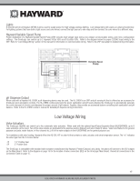
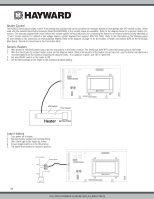
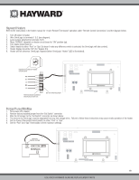
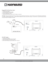
Hayward Variable Speed Pump (VSP) Wiring Hayward VSPs connect to the OmniLogic's Low Speed Bus. Refer to your EcoStar manual for proper low voltage communication wiring between the OmniLogic and the Hayward Variable Speed Pump. Temperature Sensors The OmniLogic utilizes 10K ohm thermistor type sensors and provides three inputs. Three sensors (water temperature, air temperature and solar or dual equipment spa temperature) are included. If the OmniLogic is being used to control a solar heating system, the solar sensor is required. If dual equipment will be used, the dual equipment spa sensor is required. If both solar and dual equipment are desired, another temperature sensor must be purchased separately. The sensors are provided with a 15 ft. cable. If a longer cable is required, contact the Hayward service dept. (908-355-7995) for information on suitable cable types and splices. Wire sensors as shown below. Record all connections using the table on page 15. External Input Interlock The External Input Interlock provides a means to turn the filter pump or other component on/off when certain conditions exists. A normally open or normally closed on/off external device must be connected to the OmniLogic as shown below. After properly configuring the OmniLogic (see Configuration Wizard in Operation Manual), the filter pump and/or desired pool component will be forced on or off when the device is active. Record all connections using the table on page 15. 21 USE ONLY HAYWARD GENUINE REPLACEMENT PARTS
-
 1
1 -
2
-
3
-
4
-
5
-
6
-
7
-
8
-
9
-
10
-
11
-
12
-
13
-
14
-
15
-
16
-
17
-
18
-
19
-
 20
20 -
 21
21 -
 22
22 -
 23
23 -
 24
24 -
 25
25 -
 26
26 -
 27
27 -
 28
28 -
 29
29 -
 30
30 -
31
-
32
-
33
-
34
-
35
-
36
-
37
-
38
-
39
-
40
-
41
-
42
-
43
-
44
 |
 |
