Hayward OmniLogic Installation Manual - Page 26
Remote Terminal, HL-CHEM ORP and pH Sensing Kit
 |
View all Hayward OmniLogic manuals
Add to My Manuals
Save this manual to your list of manuals |
Page 26 highlights
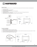
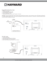
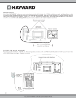
Remote Terminal Up to 2 wired HLWALLMOUNT touchscreen remote terminals can be wired to the OmniLogic. Use 24AWG (or better) four conductor cable (typically phone cable) to connect the wired remote terminal to the OmniLogic's High Speed Bus as shown below. Note that the screw connections on both the OmniLogic main unit and the wired remote terminal are numbered: Connect 1 to 1, 2 to 2, etc. as shown in the diagram below. Although the High Speed Bus has 5 screw terminals, screw #5 is not used. Refer to the HLWALLMOUNT manual for maximum distances and complete installation instructions. Connect screw terminals "1" to "1", "2" to "2", etc. x 4321 OmniLogic Main Board Remote Terminal 4321 Refer to HLWALLMOUNT manual for max distance HL-CHEM ORP and pH Sensing Kit Plug in the connector from the HL-CHEM into one of the Low Speed Bus connectors on the main PCB in the OmniLogic Control Center as shown below. Refer to the HLCHEM manual for complete installation instructions. Connect Probe Cell cable here Route cable through access hole Route though knockout 22 USE ONLY HAYWARD GENUINE REPLACEMENT PARTS
-
 1
1 -
2
-
3
-
4
-
5
-
6
-
7
-
8
-
9
-
10
-
11
-
12
-
13
-
14
-
15
-
16
-
17
-
18
-
19
-
20
-
 21
21 -
 22
22 -
 23
23 -
 24
24 -
 25
25 -
 26
26 -
 27
27 -
 28
28 -
 29
29 -
 30
30 -
 31
31 -
32
-
33
-
34
-
35
-
36
-
37
-
38
-
39
-
40
-
41
-
42
-
43
-
44
 |
 |
