Hayward PL-PLUS Installation Manual - Page 14
Configuration Menu
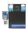 |
View all Hayward PL-PLUS manuals
Add to My Manuals
Save this manual to your list of manuals |
Page 14 highlights
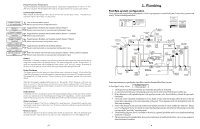
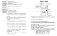
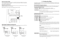
General Purpose Outlet If desired, a duplex receptacle with weatherproof cover (supplied by installer) may be installed in the knockouts on the lower right side of the Aqua Plus enclosure. Per code, the receptacle should be a GFCI type. Alternatively, connect a standard receptacle to a GFCB. Aqua Plus Control Power The Aqua Plus requires 120VAC, 2A power to operate the control logic circuits and the chlorinator. This power should be connected to one of the circuit breakers. ! WARNING: 120VAC only (permanent damage if connected to 240V) 120, 2VA Factory Prewired Neutral L1 Field Wired High Voltage (120/240V) Pool Equipment All Aqua Plus relays are double pole (they make/break both "legs" of 240V circuits) and are rated at 3HP/30A at 240V (1½HP/30A at 120V). Refer to the diagram below for typical relay wiring. 240 VAC Load 120 VAC Load 120 VAC Load Wiring relays for 240 VAC Pool Equipment Wiring relays for 120 VAC Pool Equipment 11 Wiring GFCB for 120 VAC Pool Equipment 5. Configuration Menu After plumbing and wiring are complete, the Aqua Plus MUST BE CONFIGURED before attempting to operate. Configuration information is entered at the keypad and "tells" the Aqua Plus what equipment is connected and how each should be controlled. Accessing the Configuration Menus Configuring the Aqua Plus requires that you navigate through the Configuration Menu and input various information. For more detailed information about using the Aqua Plus menu system, refer to the Operation Manual. To access the Configuration Menu Configuration Menu-Locked Press repeatedly until "Configuration Menu" is displayed Press BOTH buttons SIMULTANEOUSLY for 5 seconds to unlock Configuration Menu-Unlocked Move to configuration menu items NOTE: The configuration menu automatically "locks" after 2 minutes of no buttons being pressed to prevent unauthorized people from changing the control logic inadvertently and possibly damaging the pool equipment or causing a "call back" to fix the configuration. Configuration Menu Items Each item needs to be programmed and may contain additional sub-menu items. Refer to the following pages for information on programming. Chlor. Config. + to view/change Chlorinator Enabled Display Salt Cell Type T-CELL-15 Push to access Chlorinator option Move to next configuration menu Toggle between Chlorinator Enabled and Disabled (default) Move to next menu item Toggle between Display Salt (default) and Minerals Move to previous/next configuration menu Rotates between available Cell types Move to next menu item Chlorinator The Aqua Plus is shipped with the chlorinator enabled. The cell and flow switch must be installed and the Aqua Plus will automatically chlorinate both the pool and spa according to the desired output setting (see Settings Menu in the Operation manual). If disabled, all displays relating to the chlorinator will be suppressed. When the chlorinator is enabled, the Aqua Plus will automatically detect and control any Aqua Rite(s) that is installed in the system. Display Allows for the display of salt (default) or mineral values. Cell Type Selection The Cell Type Menu appears after "Display Salt/Minerals" in the Chlorinator Configuration Menu. The options are T-CELL-15 (default), T-CELL-9, T-CELL5 or T-CELL-3. Make the proper selection based on the chlorinator cell that is used in your system (the Aqua Plus includes the T-CELL-15). Refer to the information below. "T-CELL-3" = T-CELL-3, GLX-CELL-3-W "T-CELL-9" = T-CELL-9, GLX-CELL-9-W "T-CELL-5" = GLX-CELL-5, GLX-CELL-5-W "T-CELL-15" = T-CELL-15, GLX-CELL-15-W Chemistry Config. Wizard + to enter Press to access Chemistry Config. Wizard Move to previous/next menu item Chemistry Configuration Wizard Requires use of the optional AQL-CHEM Sensing Kit. Following the steps of the Chemistry Config. Wizard will set up the AQL-CHEM to sense ORP and pH levels and, if chlorination is used, can configure the Aqua Plus to generate the correct amount of chlorine to properly sanitize the pool. Refer to the AQL-CHEM manual for more detailed information. 20
-
 1
1 -
2
-
3
-
4
-
5
-
6
-
7
-
8
-
 9
9 -
 10
10 -
 11
11 -
 12
12 -
 13
13 -
 14
14 -
 15
15 -
 16
16 -
 17
17 -
 18
18
 |
 |
