Hayward PL-PLUS Installation Manual - Page 18
Pro Logic Output, VSP Address
 |
View all Hayward PL-PLUS manuals
Add to My Manuals
Save this manual to your list of manuals |
Page 18 highlights
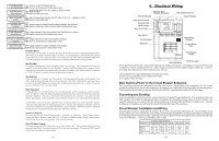
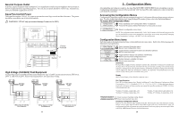
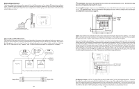
Pentair/Purex/MiniMax 1. Turn power off to heater. 2. Remove factory installed jumper from the "Ext Switch" connector. 3. Wire the Aqua Plus to the "Ext Switch" connector as shown below. 4. The wires to the Aqua Plus must be separated from any line voltage wires. Failure to follow these instructions may cause erratic operation of the heater. 5. Set the Power (Thermostat Select) switch to either "Pool" or "Spa". 6. Set the "Pool" and "Spa" thermostats to their maximum settings. Remove Factory Jumper Ext. Switch MINIMAX Raypak RP2100 Pool/Spa Heater 1. Turn power off to heater. 2. Push the mode button to "spa" mode. 3. Set the temperature to the maximum. 4. Push the mode button to "OFF". 5. Lastly, plug the prewired connector in the P7 position on the board. ! IMPORTANT: The heater will display "OFF" when it is being remotely controlled by the Aqua Plus. Some homeowners see the "OFF" display and, thinking this is a mistake, change the mode to "POOL" or "SPA" which then disables the remote control by the Aqua Plus. To prevent this: Remove the heater touch pad connector (P5) which will disable the touchpad. Black Orange Stripe Orange Black Stripe Light Blue P7 Drawing is for digital heater. If heater is a millivolt (analog), run red wires from Fireman's Switch to heater relay. RAYPAK RP2100 15 STA-RITE Heater 1. Turn power off to heater. 2. Remove upper jacket and open the control box. 3. Remove the jumper for the "fireman's switch. 4. Wire to the Aqua Plus using wire rated for 105°C minimum. Fireman's Switch Operating 'Control Terminal Board STA-RITE Hayward Variable Speed Pump (VSP) Wiring and Address Setting Refer to your TriStar or EcoStar manual(s) for proper low voltage communication wiring between the Aqua Plus and the Hayward Variable Speed Pump. A pump address must be configured for each VSP used in the system. This address is entered into the VSP's configuration menu. Refer to the table below to determine which address to use for your specific pump and Aqua Plus. Select the proper address based on which output will be used and the model VSP you are configuring. Pro Logic Output This is the output used to control the VSP. Note that the VSP should be wired to this output's corresponding relay. FILTER AUX1 LIGHTS VSP Address This is the name that should be selected under "Set COMM bus address" (EcoStar) or "*H.Comm ADDR." (TriStar) within the VSP's Configuration Menu. "001" - Tristar "Pool Filter" - EcoStar "002" - Tristar "Aux1 / Spa Filter" - EcoStar "Lights Button" - EcoStar only AUX2 Aux2 - EcoStar only 16
-
 1
1 -
2
-
3
-
4
-
5
-
6
-
7
-
8
-
9
-
10
-
11
-
12
-
 13
13 -
 14
14 -
 15
15 -
 16
16 -
 17
17 -
 18
18
 |
 |
