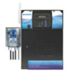
Hayward PL-PLUS Installation Manual - Page 15
External Input Interlock, Hayward Aqua Rite Chlorinator
 |
View all Hayward PL-PLUS manuals
Add to My Manuals
Save this manual to your list of manuals |
Page 15 highlights
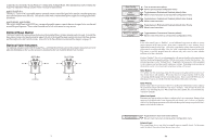
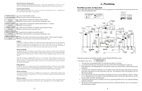
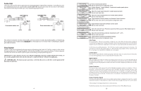
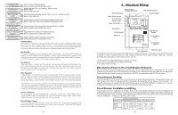
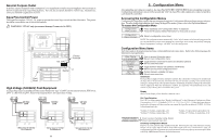
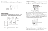
External Input Interlock The External Input Interlock provides a means to force the filter pump or an Aux output off when certain conditions exists. A normally open or normally closed on/off external device must be connected to the Aqua Plus as shown below. After properly configuring the Aqua Plus (see Configuration), the filter pump and/or desired Aux will be forced off when the device is active. SPST External Switch (either Normally Open or Normally Closed) Hayward Aqua Rite Chlorinator The Aqua Plus can control one or more Hayward Aqua Rite chlorinators when additional sanitizing capacity is required. A 4 wire connection is used to communicate to the Aqua Rite and can be wired up to 500' apart. Any outdoor rated 4 conductor cable can be used. Refer to the wiring diagrams below for proper wiring connection to the Aqua Rite. NOTE: There must be only 1 "primary" unit. All other Aqua Rite units must be configured as "secondary". Jumper Installed For Primary (Factory Default) Aqua Plus Aqua Rite (Primary) 4 GREEN 3 YELLOW 2 BLACK 1 RED Jumper Removed For Secondary(s) Aqua Rite (Secondary) Additional Aqua Rite(s) (if required) NOTE: Primary/Secondary jumper is located underneath small circuit board. GRN 4 Aqua Plus YEL BLK 3 2 RED 1 green 4 GRN Aqua Rite yellow black 3 YEL 2 BLK red 1 RED 19 ! WARNING: Do not use the Aqua Plus to control an automatic pool cover. Swimmers may become entrapped underneath the cover. Two speed filter pump: Requires 2 relays (FILTER plus one of the AUX relays) for proper operation of both speeds. ! IMPORTANT: Be sure to follow the wiring diagram below AND to configure the control logic according to the instructions on page 22. Lo Speed Hi Speed Common Ground 2-Speed Filter Pump N L2 L1 G Lights: A ground fault circuit breaker must be used to supply power for high voltage pool/spa lighting. Low voltage lights will require an external transformer. For lighting systems that have both a light source and color wheel, connect the light source to the "Lights" relay and then connect the color wheel to one of the AUX outputs. Hayward Variable Speed Pump: Proper installation of a Hayward Variable Speed Pump (VSP) includes high voltage input wiring, low voltage communication wiring, and menu configuration/settings. The Aqua Plus can control up to 2 Hayward TriStar VSPs and 4 EcoStar VSPs. Refer to the diagram below for proper input wiring to the VSP. Wiring from the 220V breaker must connect through the Aqua Plus's Filter/Lights/Aux relay. Refer to VSP Address Setting on page 16 to determine which relays can be used with your pump. The selected relay will supply input power to the VSP pump control and be on when the output is on. When the output is off, the relay will be off. Note that when the relay is off (power off to the VSP), the Aqua Plus will not display errors or diagnostics for the pump. The relay must be on for diagnostic function. Refer to the VSP manual(s) for detailed wiring information. 220 VAC input power to VSP pH Dispense Output: NOTE: The Aqua Plus can only be used with a 120VAC pH dispensing device. There are two Aqua Plus versions that require different installation techniques. Aqua Pluss operating with a software version less than 4.00 require the pigtail or pH dispensing device to be connected to an internal relay. Units using version 4.00 or later have a dedicated pH output through the screw terminals mounted on the inside of the enclosure (shown on page 10). Refer to the AQL-CHEM's ph dispense wiring instructions that relates to your particular version. 12
-
 1
1 -
2
-
3
-
4
-
5
-
6
-
7
-
8
-
9
-
 10
10 -
 11
11 -
 12
12 -
 13
13 -
 14
14 -
 15
15 -
 16
16 -
 17
17 -
 18
18
 |
 |
