Hayward W3H400FDP HCC-2000-Automated-Controller-Owners-Manual-092460RevG - Page 7
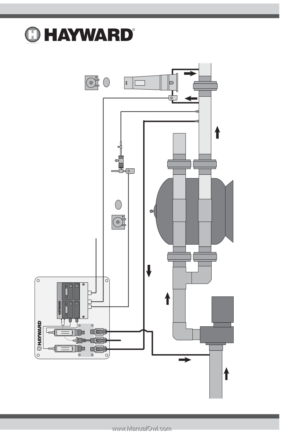
Typical HCC 2000 Installation Diagram
 |
View all Hayward W3H400FDP manuals
Add to My Manuals
Save this manual to your list of manuals |
Page 7 highlights
Typical HCC 2000 Installation Diagram: 6 USE ONLY HAYWARD GENUINE REPLACEMENT PARTS pH ORP CAT PRO15 CAT PRO25 pH Sensor ORP Sensor Flow FEED pH ALARM HCC 2000 pH/ ORP CONTROLLER ORP FEED ALARM pH ORP Setpoint Adjustment SET CALIBRATE Channel Mode Selection AUTO OFF MANUAL Setpoint Adjustment SET BREAKPOINT Channel Mode Selection AUTO OFF MANUAL HCC 2000 CONTROLLER Power Cord ORP Feed Output Effluent (to Suction) Sample Stream Influent (to Return Line) pH Feed Output Chemical Pump or CAT CO2 pH Control Solenoid Flow Cell / Flow Sensor Bypass Line Flow Flow Flow WASTE Chemical Pump or Erosion Feeder Solenoid Main Drain and Skimmer SUCTION LINE Flow PUMP FILTER RETURN LINE Flow ALL CHEMICALS MUST BE INJECTED DOWN STREAM FROM HEATER AND FLOW CELL Pressure Differential
-
 1
1 -
 2
2 -
 3
3 -
 4
4 -
 5
5 -
 6
6 -
 7
7 -
 8
8 -
 9
9 -
 10
10 -
 11
11 -
 12
12 -
13
-
14
-
15
-
16
-
17
-
18
-
19
-
20
-
21
-
22
-
23
-
24
 |
 |