HealthRider 875p Treadmill Uk Manual - Page 8
Right Foam Grip 43 as described above. Note: Make
 |
View all HealthRider 875p Treadmill manuals
Add to My Manuals
Save this manual to your list of manuals |
Page 8 highlights
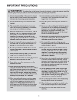
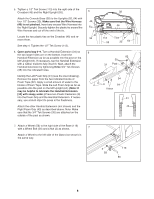
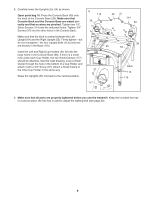
5. Tighten a 1/2" Tek Screw (113) into the right side of the Crossbar (46) and the Right Upright (55). 5 Attach the Console Base (38) to the Uprights (55, 64) with four 1/2" Screws (33). Make sure that the Wire Harness 49 (49) is not pinched. Insert any excess Wire Harness into the Right Upright. Securely tighten the plastic tie around the Tie Wire Harness and cut off the end of the tie. Locate the two plastic ties on the Crossbar (46) and remove them. 33 See step 4. Tighten the 1/2" Tek Screw (113). 6. Open parts bag 6-9. Turn a Handrail Extension (34) so 6 the two larger holes are on the bottom. Insert the Handrail Extension as far as possible into the post on the left Upright (64). If necessary, tap the Handrail Extension with a rubber mallet to fully insert it. Next, attach the Handrail Extension by tightening three 3/4" Tek Screws (35) into the indicated holes. Identify the Left Foam Grip (31) (see the inset drawing). Remove the paper from the two indicated blocks of Foam Tape (82). Apply a small amount of water to the blocks of Foam Tape. Slide the Left Foam Grip as far as possible onto the post on the left Upright (64). (Note: It may be helpful to lubricate the Handrail Extension [34] with soapy water.) Press two Plastic Fasteners (9) into the Foam Grip and the Handrail Extension. If necessary, use a blunt object to press in the Fasteners. Attach the other Handrail Extension (not shown) and the Right Foam Grip (43) as described above. Note: Make sure that the 3/4" Tek Screws (35) are attached on the outside of the post as shown. 7. Attach a Wheel (58) to the right side of the Base (116) with a Wheel Bolt (56) and a Nut (3) as shown. 7 Attach a Wheel to the left side of the Base (not shown) in the same way. 38 46 113 Ties 55 33 64 82 35 31 Post 34 9 64 Holes 31 43 3 58 116 56 8
-
 1
1 -
2
-
 3
3 -
 4
4 -
 5
5 -
 6
6 -
 7
7 -
 8
8 -
 9
9 -
 10
10 -
 11
11 -
 12
12 -
 13
13 -
14
-
15
-
16
-
17
-
18
-
19
-
20
-
21
-
22
-
23
-
24
-
25
-
26
-
27
-
28
-
29
-
30
-
31
-
32
-
33
-
34
-
35
 |
 |
