HealthRider 875p Treadmill Uk Manual - Page 9
Insert the Left and Right Cup Holders 39, 50 into
 |
View all HealthRider 875p Treadmill manuals
Add to My Manuals
Save this manual to your list of manuals |
Page 9 highlights
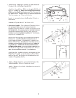
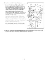
8. Carefully lower the Uprights (55, 64) as shown. Open parts bag 10. Press the Console Back (40) onto the back of the Console Base (38). Make sure that Console Back and the Console Base are mated correctly and that no wires are pinched. Tighten two 1/2" Silver Screws (114) into the indicated holes. Tighten 3/4" Screws (37) into the other holes in the Console Back. Make sure that the deck is centred between the Left Upright (64) and the Right Upright (55). Firmly tighten-but do not overtighten-the four Upright Bolts (112) (only two are shown) in the Base (116). Insert the Left and Right Cup Holders (39, 50) into the large holes in the Console Base (38). If there is a small hole under each Cup Holder, the two Small Clamps (117) should be attached. See the inset drawing. Loop a Small Clamp through the hole in the bottom of a Cup Holder and attach it with a 3/4" Screw (37). Attach a Small Clamp to the other Cup Holder in the same way. Raise the Uprights (55, 64) back to the vertical position. 8 114 39 40 37 114 50 38 55 64 37 117 Deck 112 116 9. Make sure that all parts are properly tightened before you use the treadmill. Keep the included hex key in a secure place; the hex key is used to adjust the walking belt (see page 26). 9
-
 1
1 -
2
-
3
-
 4
4 -
 5
5 -
 6
6 -
 7
7 -
 8
8 -
 9
9 -
 10
10 -
 11
11 -
 12
12 -
 13
13 -
 14
14 -
15
-
16
-
17
-
18
-
19
-
20
-
21
-
22
-
23
-
24
-
25
-
26
-
27
-
28
-
29
-
30
-
31
-
32
-
33
-
34
-
35
 |
 |
