HealthRider C535e Elliptical English Manual - Page 7
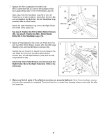
Pivot Axle 97 and to two M8 Large Washers 53. Next
 |
View all HealthRider C535e Elliptical manuals
Add to My Manuals
Save this manual to your list of manuals |
Page 7 highlights
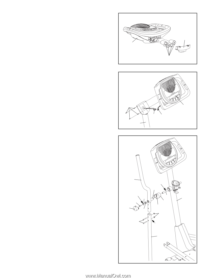
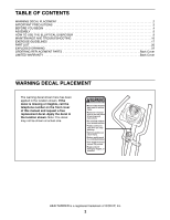
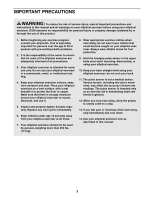
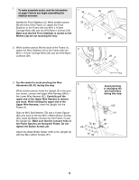
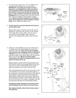
4. The Console (5) requires four 1.5V "D" batteries (not included); alkaline batteries are recommended. IMPORTANT: If the elliptical exerciser has been exposed to cold temperatures, allow it to warm to room temperature before inserting batteries into the Console. If you do not do this, the console displays or other electronic components may become damaged.Remove the battery cover from the Console. Next, insert four batteries into the battery compartments. Make sure that the batteries are oriented as shown by the diagrams inside the battery compartments. Then, replace the battery cover. 4 5 5. Tip: Be careful to avoid pinching the wire harnesses during this step. While another person holds the Console (5) near the Upright (2), connect the wire harness on the Console to the Upper Wire Harness (86). Insert the excess wire harness into the Upright. Next, attach the Console to the Upright with four M4 x 16mm Screws (66). 5 66 2 Battery Cover Batteries 5 86 Wire Harness 6. Identify the Left Handlebar (9), which is marked with an "L" sticker. Insert the Left Handlebar into one of the 6 Handlebar Legs (79); make sure that the Handlebar Leg is turned so the hexagonal holes are oriented as indicated. Attach the Left Handlebar to the Handlebar Leg with two M8 x 45mm Button Bolts (50) and two M8 Nylon Locknuts (46). Make sure that the Nylon Locknuts are set inside the hexagonal holes. Do not tighten the Button Bolts yet. Apply a generous amount of the included grease to the Pivot Axle (97) and to two M8 Large Washers (53). Next, insert the Pivot Axle into the Upright (2) and center it. Apply more grease to both ends of the Pivot Axle. Slide a Handlebar Spacer (25) onto the short tube on the Left Handlebar (9), and rotate the Handlebar Spacer so the small arrow is pointing toward the floor. Next, slide the Left Handlebar onto the left end of the Pivot Axle (97). Finger tighten an M8 x 25mm Patch Screw (22) with an M8 Large Washer (53) and a Wave Washer (95) into the end of the Pivot Axle. Then, attach a Handlebar Cap (23) by pressing its small tabs into the Handlebar Spacer. Assemble the Right Handlebar (not shown) and the other Handlebar Leg (not shown) in the same way. 9 Grease Tube Grease 53 22 97 2 25 23 Arrow 95 46 50 Hexagonal Holes 79 Now, tighten both M8 x 25mm Patch Screws (22) at the same time. 7
-
 1
1 -
 2
2 -
 3
3 -
 4
4 -
 5
5 -
 6
6 -
 7
7 -
 8
8 -
 9
9 -
 10
10 -
 11
11 -
 12
12 -
13
-
14
-
15
-
16
-
17
-
18
-
19
-
20
-
21
-
22
-
23
-
24
 |
 |