HP 15-ay100 Maintenance and Service Guide - Page 91
Use the following image to determine proper cable routing for the display cable and the wireless
 |
View all HP 15-ay100 manuals
Add to My Manuals
Save this manual to your list of manuals |
Page 91 highlights
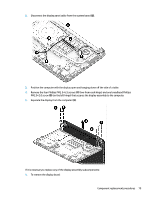
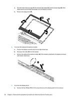
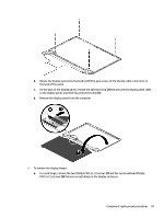
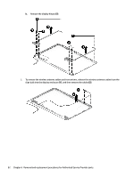
6. To remove the display/webcam cable, remove the cable from the clips built into the display enclosure (1), and then remove the cable from the display enclosure (2). 7. If replacing the display enclosure, be sure that the subcomponents (including the webcam/microphone module, the antenna receivers, and all associated cables and hardware) are transferred to the new enclosure. 8. Use the following image to determine proper cable routing for the display cable and the wireless antennas. (1): Display hinge (2): Display cable routing path (3): Antenna cable routing path Reverse this procedure to reassemble and install the display assembly. Component replacement procedures 83
-
 1
1 -
2
-
3
-
4
-
5
-
6
-
7
-
8
-
9
-
10
-
11
-
12
-
13
-
14
-
15
-
16
-
17
-
18
-
19
-
20
-
21
-
22
-
23
-
24
-
25
-
26
-
27
-
28
-
29
-
30
-
31
-
32
-
33
-
34
-
35
-
36
-
37
-
38
-
39
-
40
-
41
-
42
-
43
-
44
-
45
-
46
-
47
-
48
-
49
-
50
-
51
-
52
-
53
-
54
-
55
-
56
-
57
-
58
-
59
-
60
-
61
-
62
-
63
-
64
-
65
-
66
-
67
-
68
-
69
-
70
-
71
-
72
-
73
-
74
-
75
-
76
-
77
-
78
-
79
-
80
-
81
-
82
-
83
-
84
-
85
-
 86
86 -
 87
87 -
 88
88 -
 89
89 -
 90
90 -
 91
91 -
 92
92 -
 93
93 -
 94
94 -
 95
95 -
 96
96 -
97
-
98
-
99
-
100
-
101
-
102
-
103
-
104
-
105
-
106
-
107
-
108
-
109
-
110
-
111
-
112
-
113
-
114
-
115
-
116
-
117
-
118
-
119
-
120
-
121
-
122
-
123
-
124
-
125
-
126
-
127
-
128
-
129
-
130
-
131
-
132
-
133
-
134
-
135
-
136
-
137
-
138
 |
 |
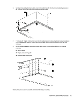
6.
To remove the display/webcam cable, remove the cable from the clips built into the display enclosure
(1)
, and then remove the cable from the display enclosure
(2)
.
7.
If replacing the display enclosure, be sure that the subcomponents (including the webcam/microphone
module, the antenna receivers, and all associated cables and hardware) are transferred to the new
enclosure.
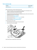
8.
Use the following image to determine proper cable routing for the display cable and the wireless
antennas.
(1)
: Display hinge
(2)
: Display cable routing path
(3)
: Antenna cable routing path
Reverse this procedure to reassemble and install the display assembly.
Component replacement procedures
83