HP 15-ay100 15-ay099 250 G5 Notebook PC 256 G5 Notebook PC - Maintenance and S - Page 75
Heat sink assembly, Remove the optical drive see
 |
View all HP 15-ay100 manuals
Add to My Manuals
Save this manual to your list of manuals |
Page 75 highlights
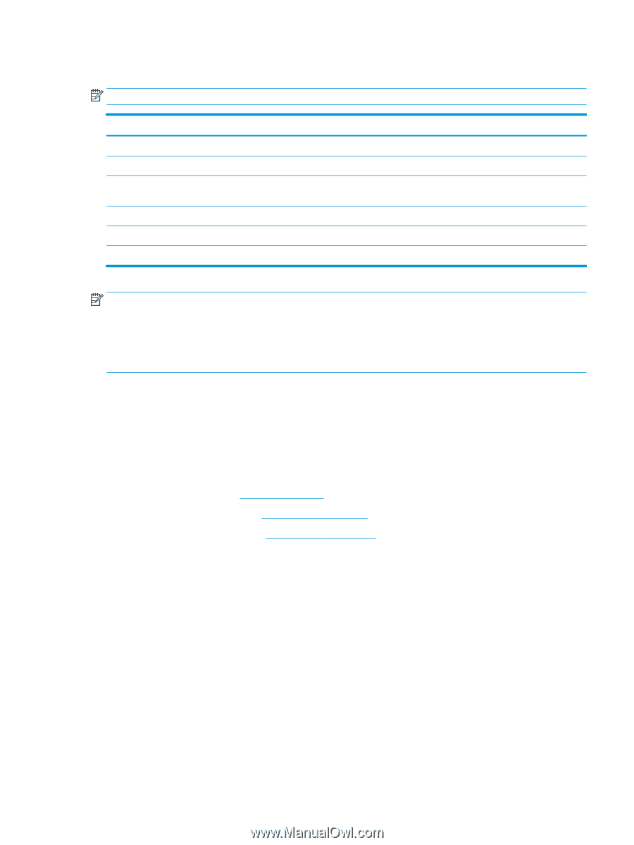
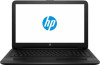
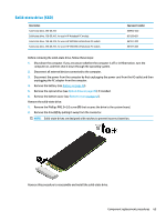
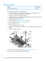
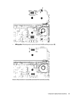
Heat sink assembly NOTE: The heat sink assembly spare part kit includes replacement thermal materials. Description Spare part number Heat sink for use in models with discrete graphics memory and 5th or 6th generation Intel Core processors 815238-001 Heat sink for use in models with UMA graphics memory and 5th or 6th generation Intel Core processors 815237-001 Heat sink for use in models with discrete graphics memory and 6th generation Intel Pentium or Celeron processors 816604-001 Heat sink for use in models with UMA graphics and 6th generation Intel Pentium or Celeron processors 854954-001 Heat sink for use in models with discrete graphics memory and 7th generation Intel processors 903806-001 Heat sink for use in models with UMA graphics memory and 7th generation Intel processors 903807-001 NOTE: To properly ventilate the computer, allow at least 7.6 cm (3.0 in) of clearance on the left side of the computer. The computer uses an electric fan for ventilation. The fan is controlled by a temperature sensor and is designed to turn on automatically when high temperature conditions exist. These conditions are affected by high external temperatures, system power consumption, power management/battery conservation configurations, battery fast charging, and software requirements. Exhaust air is displaced through the ventilation grill located on the left side of the computer. Before removing the heat sink assembly, follow these steps: 1. Shut down the computer. If you are unsure whether the computer is off or in Hibernation, turn the computer on, and then shut it down through the operating system. 2. Disconnect all external devices connected to the computer. 3. Disconnect the power from the computer by first unplugging the power cord from the AC outlet and then unplugging the AC adapter from the computer. 4. Remove the battery (see Battery on page 48). 5. Remove the optical drive (see Optical drive on page 49), if installed. 6. Remove the bottom cover (see Bottom cover on page 52). To remove the heat sink assembly: 1. Refer to the following heat sink removal image that matches your computer. 2. Loosen the screws on the heat sink (1) that secure the heat sink assembly to the system board. Component replacement procedures 67
-
 1
1 -
2
-
3
-
4
-
5
-
6
-
7
-
8
-
9
-
10
-
11
-
12
-
13
-
14
-
15
-
16
-
17
-
18
-
19
-
20
-
21
-
22
-
23
-
24
-
25
-
26
-
27
-
28
-
29
-
30
-
31
-
32
-
33
-
34
-
35
-
36
-
37
-
38
-
39
-
40
-
41
-
42
-
43
-
44
-
45
-
46
-
47
-
48
-
49
-
50
-
51
-
52
-
53
-
54
-
55
-
56
-
57
-
58
-
59
-
60
-
61
-
62
-
63
-
64
-
65
-
66
-
67
-
68
-
69
-
 70
70 -
 71
71 -
 72
72 -
 73
73 -
 74
74 -
 75
75 -
 76
76 -
 77
77 -
 78
78 -
 79
79 -
 80
80 -
81
-
82
-
83
-
84
-
85
-
86
-
87
-
88
-
89
-
90
-
91
-
92
-
93
-
94
-
95
-
96
-
97
-
98
-
99
-
100
-
101
-
102
-
103
-
104
-
105
-
106
-
107
-
108
-
109
-
110
-
111
-
112
-
113
-
114
-
115
-
116
-
117
-
118
-
119
-
120
-
121
-
122
-
123
-
124
-
125
-
126
-
127
-
128
-
129
-
130
-
131
-
132
-
133
-
134
-
135
-
136
-
137
-
138
 |
 |